


6 308768
Installation
General Information
NOTE: Reference numbers and letters in parentheses
in the text refer to the callouts in the figures and the
parts drawing.
NOTE: Always use Genuine Graco Parts and Acces-
sories, available from your Graco distributor. If you
supply your own accessories, be sure they are ade-
quately sized and pressure-rated for your system.
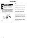
Prepare the Operator
All persons who operate the equipment must be
trained in the safe, efficient operation of all system
components as well as the proper handling of all fluids.
All operators must thoroughly read all instruction
manuals, tags, and labels before operating the equip-
ment.
The following manuals are included with this equip-
ment:
D 3A1450, 3:1 President Pump
D 306982, President Air Motor
D 307273, 307282, or 308918, Fluid Filter
D 307068, Fluid Ball Valves
D 308401, Back Pressure Regulator
Prepare the Site
Ensure that the wall is strong enough to support the
weight of the pump and accessories, fluid, hoses, and
stress caused during pump operation.
Ensure that you have an adequate compressed air
supply. Refer to the performance chart on page 21 to
find the air consumption.
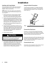
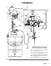
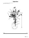
Refer to Fig. 2 on page 9. Bring a compressed air
supply line (A) from the air compressor to the pump
location. Be sure all air hoses are properly sized and
pressure-rated for your system. Use only electrically
conductive hoses. The air hose should have a 3/8
npt(m) thread.
Install a bleed-type shutoff valve (B) in the air line to
isolate the air line components for servicing. Install a
moisture trap and drain valve (C) to help remove
moisture and contaminants from the compressed air
supply.
Keep the site clear of any obstacles or debris that
could interfere with the operator’s movement.
Have a grounded, metal pail available for use when
flushing the system.