


308200 17
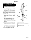
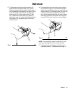
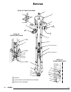
Service
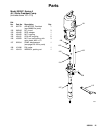
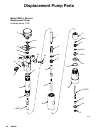
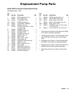
Reassembly
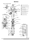
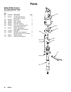
Refer to Fig. 8 for reassembly.
1. Place an 8 mm (5/16 in.) dia. brass rod lengthwise
in a vise. Install a new piston seal (14*) on the
piston seat (15). Apply thread lubricant to the
threads of the piston guide (12). Place the piston
guide (12) securely on the brass rod. Using a 22
mm crow’s-foot, screw the piston seat (15) into the
piston guide. Torque to 35–41 N.m (26–30 ft-lb).
2. If it was necessary to remove the priming piston
rod (21) from the piston (13), apply thread lubricant
to the female threads of the piston. Place the flats
of the piston (13) in a vise. Hold the flats of the rod
with an 8 mm wrench, and screw the rod into the
piston. Torque to 35-41 N.m (26-30 ft-lb). Be
careful not to create burrs on the flats of the rod.
3. Use a vise with soft jaws to hold the flats of the
displacement rod (1). Install the assembled piston
guide/seat on the piston (13). Apply thread lubri-
cant to the female threads of the piston, and screw
the piston assembly onto the rod, using a 15 mm
wrench on the piston flats. Torque to 35-41 N.m
(26-30 ft-lb). There will be a small gap between the
top of the piston (13) and the shoulder of the rod
(1).
4. Place the outlet housing (9) in a vise. If the bleeder
valve housing (BB) was removed, apply PTFE
tape to the threads and reinstall it in the outlet
housing (9), making sure the bleed hole faces
toward the bottom of the outlet housing. Then
screw the valve plug (AA) fully into the valve
housing (BB).
NOTE: The bleeder valve plug (AA) has two sets of
threads. When reassembling, be sure the plug is fully
screwed into the valve housing (BB).
NOTE: It is not ordinarily necessary to remove the
outlet nipple (7) and o-ring (8*). However, if they were
replaced because of damage, lubricate the o-ring (8*)
and place it on the nipple (7). Screw the nipple into the
outlet housing (9). Torque to 60-84 N.m (44–62 ft-lb).