


8
306–646
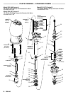
DISPLACEMENT PUMP SERVICE
Moving
parts can pinch or amputate your fingers
or
other
body parts. When the pump is operating, the
priming
piston (located at the pump intake) and the
air motor piston (located behind the air motor
shield)
move.
Therefore, NEVER operate the pump
with the air motor shield removed, and keep your
fingers
and hands away from the priming piston.
Before attempting to clear an obstruction from the
priming
piston or service the pump, follow the
Pres-
sure
Relief Procedure W
arning
on page 7 to pre
-
vent
the pump from starting accidentally
.
WARNING
Before
Y
ou Start (All Models)
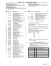
1. Repair Kit 220–861 is available. See pages 13 and
15.
For the best results, use all the new parts in the
kit,
even if the old ones look good. Repair kit parts are
indicated
in the text
and the parts list with an asterisk,
for
example (27*).
2. To reduce down time, keep spare parts on hand.
Recommended
spare parts are indicated
in the parts
list
with a double asterisk, for example (41**).
3. The gland/packing stacks (64*, 65*) are preas-
sembled.
Do not disassemble the stacks when in
-
stalling
them in the pump.
4. For air motor service and parts information, refer to
manual
307–049 for motor Model 208–356, manual
306–968
for motor Model 206–647, manual 307–304
for motor Model 215–255, or manual 307–741 for
motor
Model 220–106.
5. If
possible, flush the pump before service
with a com
-
patible solvent. Follow the Pressure Relief Proce-
dure
W
arning
on page 7. Stop the pump at the
bot
-
tom
of its stroke.
6. Disconnect
all
the hoses. Remove the pump from its
mounting
and clamp it in a vise.
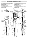
Model 204–641 Displacement Pump (Used on
Models 204–287, 215–873 and 222–248)
Disassembly
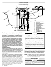
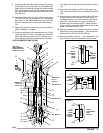
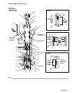
NOTE: Refer
to Fig 2 and the parts drawing.
1. Remove the cotter pin (41). Unscrew the coupling
nut (50) and the three tie rod locknuts (44). Pull the
displacement pump (2) off the air motor (1).
2. Remove
the cotter pin (42). Loosen the locknut (45).
Unscrew the connecting rod (53) from the upper cap
(33).
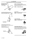
3. Insert
a 1/4 in. (6 mm) diameter rod in the
holes of the
packing nut/wet–cup (21), and loosen it. Push the
displacement rod (18) down until the priming piston
(37) clears the intake valve housing (28). Remove
the
nut (6), priming piston (37), valve plate (36)
and
plate
guide (31).
4. Unscrew
the four tie
bolts (8) and pull the intake valve
housing (28) off the pump. Pull the priming rod (32)
and displacement rod (18) out of the bottom of the
cylinder (39). Remove the pin (7) and unscrew the
priming
rod (32) from the connecting rod (20).
5. Pull
the cylinder (39) down out of the outlet housing
(26).
Inspect the inner surface of the cylinder and
the
outer surface of the displacement rod (18) for
scratches or scoring, which can cause premature
packing
wear and leaking. T
o
check, run a finger over
the
surface
or hold the part up to the light at an angle.
6. Disassemble
the intake valve (3). Clean and inspect
all parts, replacing as necessary . Check the intake
valve
seat (30) for nicks or damage.
7. Unscrew
the upper cap (33) from the connecting rod
(20). Pull the
displacement rod (18) of
f the lower cap
(19),
and remove the piston assembly from the con
-
necting
rod. Disassemble the piston.
8. Unscrew
the packing nut/wet–cup (21). Remove the
wiper
seal (66). Remove the throat
packings from the
outlet
housing (26).
9. Clean
and inspect all parts, replacing as necessary
.
Reassembly
NOTE: Refer to Fig 2 and the parts drawing during the
following
procedure.
1. See
Detail A of Fig 2. The gland/packing stack
(64*)
for
the throat is preassembled.
Do not disassemble
the
stack.
Lubricate the gland/packing stack and in
-
stall it into the outlet housing
(26).
Be sure the lips of
the v–packings are facing down.
Install the wiper
seal (66) in the groove of the wet–cup (21)
with the
lips
facing down
. Loosely install the packing nut/wet–
cup (21).
2. See Detail B of Fig 2. Install the two bearings (35*)
and the u–cup packing (56*) on the piston (38).
Be
sure
the lips of the packing are facing up.
Install the
small
o–ring (15) in the lower cap (19) and the larger
o–ring
(17) on the outside of the lower cap.
3. Install
the piston (38), valve plate (34), and lower
cap
(19)
on the connecting rod (20).
4. Insert
the connecting rod (20) into the displacement
rod
(18) so the lower cap (19) fits into the bottom of
the displacement rod. Screw the top cap (33) onto
the
connecting rod (20) until it is tight against the top
of
the displacement rod (18).
5. Install
one copper gasket (27*) in
the outlet housing
(26). Screw the priming rod (32) into the connecting
rod (20) and secure with the pin (7). Push the dis-
placement rod (18) and priming rod (32) up into the
outlet
housing (26)
so the top of the displacement rod
just protrudes from the packing nut/wet–cup (21).
Lubricate the priming rod (32).
6. Install
the cylinder (39) in the outlet housing (26), be
-
ing careful not to scratch the polished inner surface
of
the cylinder
.
7. See Detail C of Fig 2. Slide the intake valve gland/
packing
stack (65*) into the intake valve seal housing
(3).
Do not disassemble the stack.
Be sure the lips
of
the v–packings are facing up.
T
ighten the packing
nut
(1
1). Install the valve seat
(30) in the intake valve
housing (28). Place the intake valve seal housing (3)
on
the seat (30).
8. Install two copper gaskets (27*) on the intake valve
stop
(29). Install the stop
in the intake valve housing
(28).