


10
306–646
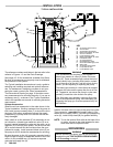
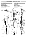
Model 222–638 Displacement Pump
(Used on Models 222–526, 222–539, 223–984
and 223–991)
NOTE: Before beginning, read “Before Y ou Start” on
page
8.
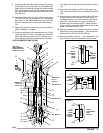
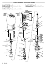
Disassembly
NOTE: Refer to Fig 3 and the parts drawing during the
following
procedure.
1. Remove the cotter pin (41). Unscrew the coupling
nut (50) and the three tie rod locknuts (44). Pull the
displacement pump (2) off the air motor (1).
2. Remove
the cotter pin (42). Loosen the locknut (45).
Unscrew
the connecting rod (53) from the displace
-
ment rod (60).
3. Insert
a 1/4 in. (6 mm) diameter rod in the
holes of the
packing nut/wet–cup (21), and loosen it. Push the
displacement rod (60) down until the priming piston
(37) clears the intake valve housing (28). Remove
the
nut (6), priming piston (37), valve plate (36)
and
plate
guide (31).
4. Unscrew
the four tie
bolts (8) and pull the intake valve
housing (28) off the pump. Pull the priming rod (62)
and displacement rod (60) out of the bottom of the
cylinder (59). Remove the pin (7) and unscrew the
priming rod (62) from the adapter (61).
5. Pull
the cylinder (59) down out of the outlet housing
(26).
Inspect the inner surface of the cylinder and
the
outer surface of the displacement rod (18) for
scratches or scoring, which can cause premature
packing
wear and leaking. T
o
check, run a finger over
the
surface
or hold the part up to the light at an angle.
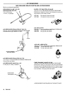
6. Disassemble
the intake valve (3). Clean and inspect
all parts, replacing as necessary . Check the intake
valve
seat (30) for nicks or damage.
7. Unscrew
the adapter (61) from the displacement
rod
(60). Remove and inspect the piston (38). Disas-
semble
the piston.
8. Unscrew
the packing nut/wet–cup (21). Remove the
wiper
seal (66). Remove the throat
packings from the
outlet
housing (26).
9. Clean
and inspect all parts, replacing as necessary
.
Reassembly
NOTE: Refer to Fig 3 and the parts drawing during the
following
procedure.
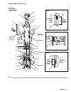
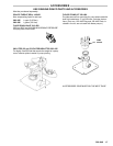
1. See
Detail A of Fig 3. The gland/packing stack
(64*)
for
the throat is preassembled.
Do not disassemble
the
stack.
Lubricate the gland/packing stack and in
-
stall it into the outlet housing
(26).
Be sure the lips of
the v–packings are facing down.
Install the wiper
seal (66) in the groove of the wet–cup (21)
with the
lips
facing down
. Loosely install the packing nut/wet–
cup (21).
2. See Detail B of Fig 3. Install the two bearings (35*)
and the u–cup packing (56*) on the piston (38).
Be
sure
the lips of the packing are facing up.
3. Install the piston (38), valve plate (34), and adapter
(61)
on the displacement rod (60).
4. Thread
the
connecting rod (62) into the adapter (61)
and
secure with the pin (7).
5. Install
one copper gasket (27*) in
the outlet housing
(26).
Push the displacement rod (60) and priming
rod
(62)
up into the outlet housing (26) so the top of the
displacement rod just protrudes from the packing
nut/wet–cup
(21). Lubricate the priming rod (62).
6. Install
the cylinder (59) in the outlet housing (26), be
-
ing careful not to scratch the polished inner surface
of
the cylinder
.
7. See Detail C of Fig 3. Slide the intake valve gland/
packing
stack (65*) into the intake valve seal housing
(3).
Do not disassemble the stack.
Be sure the lips
of
the v–packings are facing up.
T
ighten the packing
nut
(1
1). Install the valve seat
(30) in the intake valve
housing (28). Place the intake valve seal housing (3)
on
the seat (30).
8. Install two copper gaskets (27*) on the intake valve
stop
(29). Install the stop
in the intake valve housing
(28).
9. Carefully
guide
the intake valve housing (28) up over
the
priming rod (62) and install it on the cylinder (59).
Insert
the four tie bolts (8) through the outlet housing
(26)
and engage the holes in the intake valve hous
-
ing. T
orque the tie bolts oppositely and evenly to 60
ft–lb (82 N.m).
10. Install
the
plate guide (31), plate (36), priming piston
(37)
and
nut (6) on the priming rod (62). If necessary
,
push down on the displacement rod (60) to provide
sufficient clearance from the intake valve housing
(28).
11.
T
ighten the packing nut/wet–cup (21) just enough to
prevent
leakage – no tighter
.
12. Check
the alignment of the displacement rod (60) by
inserting
a size
E (0.254 in. diameter) drill shank be
-
tween the packing nut/wet–cup (21) and the rod. If
the drill shank cannot be passed freely around the
rod,
tighten the
tie bolt (8) on the side which is bind
-
ing.
13. Screw
the connecting rod (53) into the top of the dis
-
placement rod (60). Insert the cotter pin (42) and
tighten
the locknut (45).
14. Align
the pump
outlet on the outlet housing (26) with
the optional outlet at the base of the air motor (1).
Loosely screw the tie rod locknuts (44) onto the tie
rods (52). Lubricate the o–ring (47) and the top
thread of the connecting rod (53). TIghten the cou-
pling
nut (50) to attach the displacement pump to the
motor.
Insert the cotter pin (41).
15. Start
the pump and run it slowly to check for binding.
Adjust the tie rods as necessary , then torque the
locknuts
(44) to 40–50 ft–lb (54–68 N.m).
16. Reconnect the fluid and air lines. Reconnect the
ground
wire if it was disconnected during service.