


10
3. Use #18 AWG wire for 24V control wiring runs not
exceeding 75 feet. Use #16 AWG wire for 24V control
wiring runs not exceeding 125 feet. Use #14 AWG
wire for 24V control wiring runs not exceeding 200
feet. Low voltage wiring may be National Electrical
Code (NEC) Class 2 where permitted by local codes.
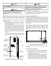
4. Route thermostat wires from sub-base terminals to
the unit. Control wiring should enter through the duct
panel (dimple marks entrance location). Connect
thermostat and any accessory wiring to low voltage
terminal block TB1 in the main control box.
NOTE: Field-supplied conduit may need to be installed
depending on unit/curb configuration. Use #18 AWG solid
conductor wire whenever connecting thermostat wires to
terminals on sub-base. DO NOT use larger than #18 AWG
wire. A transition to #18 AWG wire may be required before
entering thermostat sub-base.
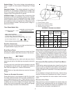
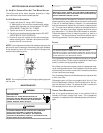
TERMINAL THERMOSTAT
Red R (24V)
Green G (Fan)
Orange O (Rev. Valve)
White W1 (Heat, 2nd)*
Yellow Y1 (Low Cool)
Purple Y2 (High Cool)
C
(
Blue
)
C
(
Common
)
*Optional field installed heat connections
CPC240
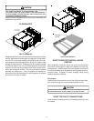
CIRCULATING AIR AND FILTERS
DUCTWORK
The supply duct from the unit through a wall may be installed
without clearance. However, minimum unit clearances must
be maintained (see “Clearances” section). The supply duct
should be provided with an access panel large enough to
inspect the air chamber downstream of the heat exchanger.
A cover should be tightly attached to prevent air leaks.
Ductwork dimensions are shown in the roof curb installation
manual.
If desired, supply and return duct connections to the unit may
be made with flexible connections to reduce possible unit
operating sound transmission.
VENTING
NOTE: Venting is self-contained.
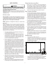
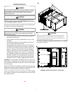
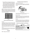
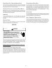
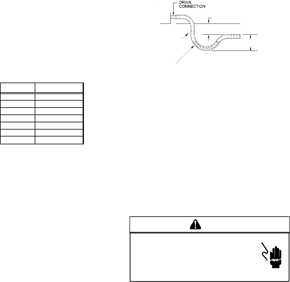
CONDENSATE DRAIN CONNECTION
CONDENSATE DRAIN CONNECTION
A 3/4” NPT drain connection is supplied for condensate pip-
ing. An external trap must be installed for proper condensate
drainage.
UNIT 2" MINIMUM
FLEXIBLE
TUBING-HOSE
OR PIPE
3" MINIMUM
A
POSITIVE LIQUID
SEAL IS REQUIRED
Drain Connection
Install condensate drain trap as shown. Use 3/4" drain line
and fittings or larger. Do not operate without trap.
HORIZONTAL DRAIN
Drainage of condensate directly onto the roof may be ac-
ceptable; refer to local code. It is recommended that a small
drip pad of either stone, mortar, wood or metal be provided to
prevent any possible damage to the roof.
CLEANING
Due to the fact that drain pans in any air conditioning unit
will have some moisture in them, algae and fungus will grow
due to airborne bacteria and spores. Periodic cleaning is
necessary to prevent this build-up from plugging the drain.
STARTUP, ADJUSTMENTS, AND CHECKS
HIGH VOLTAGE!
OND
THE
FRAME
OF
THIS
UNIT
TO
THE
BUILDING
ELECTRICAL
GROUND
BY
USE
OF
THE
GROUNDING
TERMINAL
PROVIDED
OR
OTHER
ACCEPTABLE
MEANS
. D
ISCONNECT
ALL
POWER
BEFORE
SERVICING
OR
INSTALLING
THIS
UNIT
.
T
O
AVOID
PERSONAL
INJURY
OR
DEATH
DUE
TO
ELECTRICAL
SHOCK
,
B
WARNING