5
IO-101G 06/04
The recommended procedure for processing and charge
adjustment is as follows:
1. Connect vacuum pump to both base valve service
ports.
2. Evacuate tubing and evaporator through liquid and
suction base valve ports, to 500 microns or less for a
minimum of 30 minutes. Close valve to pump and
wait 15 minutes. Vacuum should not rise above 800
microns. If unable to obtain 500 micorns, or vacuum
rises above 800 microns over a 15 minute period,
discontinue evacuation, pressurize and check for
leaks. Repair any leaks found and repeat step 2.
3. Close valve to vacuum pump and stop pump. Break
vacuum by opening liquid and suction base valves.
Fully open base valves and remove pump lines.
Connect service gauges making sure lines are purged.
4. Set thermostat system switch to “COOL” and
temperature to highest setting. Close all disconnects.
5. Set thermostat to call for cooling. Check for operation
of indoor and outdoor fans. Allow for at least 10
minutes.
6. Check charge and adjust if necessary. Refer to
appropriate “Check Charge” section.
Charge Checks
Capillary Tube/Fixed Orifice System
1. Fully open both base valves.
2. Connect service gauge manifold to base-valve service
ports being sure to purge lines. Run system at least
10 minutes to allow pressure to stabilize.
3. Temporarily install thermometer on suction (large) line
near condensing unit. Be sure of good contact
between the thermometer and line. Wrap thermometer
with insulating material to assure accurate reading.
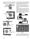
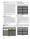
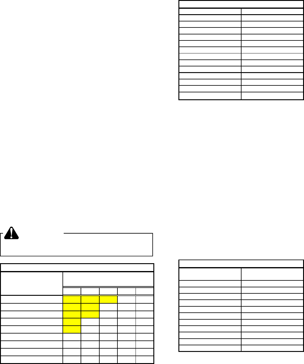
4. Refer to Table 2 for proper system superheat. Add
charge to lower superheat. Remove charge to raise
superheat.
5. Remove gauge lines carefully.
WARNING
ESCAPING LIQUID REFRIGERANT CAN CAUSE
BURNS.
AMBIENT CONDENSER
INLET TEMPERATURE
°F DRYBULB 65 70 75 80 85
100 5 5
95 5 5 5
90 7 12 18
85 5 10 17 20
80 5 12 21 26
75 5 10 17 25 29
70 5 14 20 28 32
65 13 19 26 32 35
60 17 25 30 33 37
RETURN AIR TEMPERATURE
( °F DRYBULB)
SYSTEM SUPERHEAT
TABLE 2
Superheat Determination
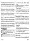
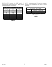
1. Read suction pressure. Using Table 3, determine
saturated suction temperature.
2. Read suction line temperature.
3. Use the following formula to determine superheat:
Superheat = Suction Line Temp. - Saturated Suction Temp.
SUCTION SATURATED SUCTION
PRESSURE PSIG TEMPERATURE °F
50 26
53 28
55 30
58 32
61 34
63 36
66 38
69 40
72 42
75 44
78 46
81 48
SATURATED SUCTION PRESSURE (R-22)
TABLE 3
Expansion Valve System
1. Fully open both base valves.
2. Connect service gauge manifold to base-valve service
parts making sure lines are purged. Run system at
least 10 minutes to allow pressure to stabalize.
3. Temporarily install the thermometer to liquid (small)
line near condensing unit. Be sure that the contact
between thermometer and line is good. Wrap
thermometer with insulating material to ensure
accurate reading.
4. Referring to Table 4, adjust charge to obtain a
temperature 12-15°F below the saturated liquid
temperature.
Example:
If the Liquid Pressure is 260 PSIG then the Saturated
Temperature will be 120°F. Adjust the Saturated
Temperature by subtracting 12-15°F. This will give you a
Liquid Line Temperature of 105° - 108°F.
LIQUID PRESSURE SATURATED
(PSIG) TEMPERATURE °F
200 102
210 105
220 108
230 111
240 114
250 117
260 120
270 123
280 126
290 128
300 131
SATURATED LIQUID TEMPERATURE
TABLE 4