


4
IO-101G 06/04
consideration is given the weather-tight integrity of the roof.
The condensing unit contains moving components and can
vibrate; therefore, sound is also a consideration in rooftop
application. Since this unit discharges warm condenser
air from the top with cooler air being drawn in three sides,
plantings can be made in relatively close proximity to the
unit. Owners should be advised to avoid lawn mower
discharge toward the unit depositing debris on the fan coil
surface reducing product efficiency.
ELECTRICAL
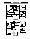
Electrical installation will consist of power supply wiring to
the condensing unit as well as control wiring between
thermostat, indoor unit and the condensing unit as shown
on wiring diagram. All wiring must be in accordance with
National Electrical Code and/or local codes that may apply.
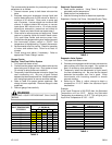
The condensing unit rating plate and the table inside the
front cover of this instruction lists pertinent electrical data
necessary for the selection of proper size electrical service
and over-current protection. The owner should be made
familiar with the location of the over-current protection,
the proper size for this application and the proper
procedure for disconnecting power service to the unit.
The condensing unit control wiring requires a 24 Volt
minimum 25 VA service from the indoor transformer as
shown on the wiring diagram.
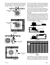
REFRIGERANT TUBING
Use only refrigerant grade (dehydrated and sealed) copper
tubing of the size indicated in Table 1 to interconnect the
condensing unit with the indoor evaporator. Take extreme
care to keep the refrigerant tubing clean and dry prior to
and during installation.
Do not remove plugs from ends of tubing until connection
is ready to be made. Suction line insulation is necessary
to prevent condensation from forming on and dropping
from suction line. Generally 3/8" wall thickness of Armflex
or equivalent is satisfactory. In severe application (hot, high
humidity areas) greater thickness may be required. Apply
suction line insulation by sliding it on the sealed tubing
before cutting and making connections.
EVAPORATOR COILS
WARNING
USE EXTREME CARE IN REMOVING THE CAPS
FROM THE SUCTION AND LIQUID LINE FITTINGS
AS THERE IS PRESSURE PRESENT. A FITTING IS
ON THE LIQUID LINE TO REMOVE PRESSURE.
WARNING
DO NOT REMOVE PROTECTIVE CAPS UNTIL
INSTALLATION HAS BEEN COMPLETED AND FINAL
CONNECTIONS ARE TO BE MADE.
Field Connection to the Valve and Valve Opening
1. Tubing should be cut square. Make sure it is round
and free of burrs at the connecting ends. Clean the
tubing to prevent contaminants from entering the
system.
2. Wrap a wet rag around the copper valve stub before
brazing.
3. Braze or silver solder the joint.
4. After brazing, quench with a wet rag to cool the joint.
Evacuate and charge the connecting lines as outlined
in these instructions.
5. Remove valve top cap. It is important to keep the cap
in a clean area to assure proper sealing once replaced.
6. Using a standard L shaped Allen wrench, break open
the valve body. To expedite opening the valve body
after it is broken, use a ratchet wrench with a short
Allen stub. Please note that it is normal to see oil on
the valve stem body once the cap is removed.
7. Replace the valve cap and tighten with a wrench
making sure that the the cap is sealed.
QUICK CONNECT COILS
Precharged System Installation
Installation procedure will differ when condensing units
are provided for use with precharged refrigerant coils and
lines. Condensing units are provided with #6 and #11
male quick connects instead of liquid and suction valves
attached to cabinet to contain the R-22 charge that is
sufficient for matching evaporator coils and 15’ of
interconnecting lines.
Coils are provided with #6 and #11 male quick connects.
Line sets are required with #6 and #11 female quick
connects on both ends. Access ports are required in the
fittings of both liquid and suction lines at condenser end.
Both coil and line sets include R-22 holding charge only.
1. Connect lines to evaporator coil before connecting to
the condensing unit locating access ports adjacent to
condensing unit.
a. Form tubing so it properly aligns with the coil
connections.
b. Remove plugs and caps from connections.
c. Check to be sure mating surfaces are clean.
d. Lubricate rubber seal with clean refrigerant oil and
thread couplings together by hand to be sure they are
not cross threaded.
e. Tighten connections using backup wrench on
stationary fitting until coupling bottoms; then tighten
1/6 turn to complete knife edge seal.
2. Connect lines to condensing unit in the same manner
as to evaporator coil. Observe same precautions.
3. After making all connections and opening valves,
check all piping for leaks.
SYSTEM START UP
Processing Checks
Condensing units are supplied R-22 charge sufficient for
typical matching evaporator and approximately 15’ of
interconnecting tubing. Condensing unit liquid and suction
valves are closed to contain the charge within the unit.