


4
PRODUCT DESIGN
NFPA 54/ANSI Z223.1 - latest edition. In Canada, the fur-
naces must be vented in accordance with the National Stan-
dard of Canada, CAN/CSA B149.1 and CAN/CSA B149.2 -
latest editions and amendments.
NOTE: The vertical height of the Category I venting system
must be at least as great as the horizontal length of the
venting system.
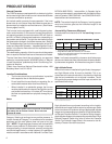
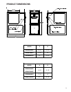
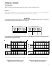
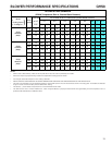
Accessibility Clearances (Minimum)
Unobstructed front clearance of 24" for servicing is recom-
mended.
SW B
1036 11
* 24" clearance for serviceability recommended.
MINIMUM CLEARANCE TO COMBUSTIBLE MATERIALS - INCHES
** Sin
g
le Wall Vent
(
SW
)
to be used onl
y
as a connector.
Refer to the venting tables outlined in the Installation Manual for
additional venting requirements.
Vent
Sides TopRear Front*
Note: In all cases accessibility clearance shall take prece-
dence over clearances from the enclosure where accessibil-
ity clearances are greater. All dimensions are given in inches.
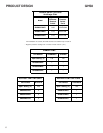
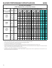
High Altitude Derate
When this furnace is installed at high altitude, the appropri-
ate High Altitude orifice kit must be installed. This is re-
quired due to the natural reduction in the density of both the
gas fuel and combustion air as altitude increases. The kit
will provide the proper design certified input rate within the
specified altitude range.
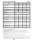
2000 3000 4000 4500 5000 6000 7000 8000
US BURNER
ORIFICE
44/55 44/55 45/56 45/56 46/57 47/58 47/58
CANADA BURNER
ORIFICE
44/55 47/57
HA-02 HIGH ALTITUDE CONVERSION KIT REQUIRED
Tabled data is based upon the furnace input being reduced for altitudes above sea level. U.S. 4% per 1,000 feet.
Canada 10% derate for 2,000-4,000 feet.
ELEVATION ABOVE SEA-LEVEL (FEET)
INPUT PER BURNER - 22,500 BTUH NATURAL GAS / 20,000 BTUH L.P.
High altitude kits are purchased according to the installa-
tion altitude and usage of either natural or propane gas. Refer
to the chart above for a tabular listing of appropriate altitude
ranges and corresponding manufacturer’s high altitude Natu-
ral Gas and Propane Gas kits. For a tabular listing of appro-
priate altitude ranges and corresponding manufacturer's High
Altitude Pressure Switch kits, refer to either the Pressure
Switch Trip Points & Usage Chart in this manual or the Ac-
cessory Charts in Service Instructions.
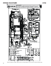
General Operation
The G*S8 furnaces are equipped with an electronic ignition
device used to light the burners and an induced draft blower
to exhaust combustion products.
An interlock switch prevents furnace operation if the inner
blower door is not in place. Keep the blower access door in
place except for inspection and maintenance. (See illustra-
tion on pages 5 and 6.)
This furnace is also equipped with a self-diagnosing elec-
tronic control module. In the event a furnace component is
not operating properly, the control module LED will flash on
and off in a factory-programmed sequence, depending on
the problem encountered. This light can be viewed through
the observation window in the blower access door. Refer to
the Troubleshooting Chart for further explanation of the LED
codes and Abnormal Operation - Integrated Ignition Control
section in the Service Instructions for an explanation of the
possible problem.
The rated heating capacity of the furnace should be greater
than or equal to the total heat loss of the area to be heated.
The total heat loss should be calculated by an approved
method or in accordance with “ASHRAE Guide” or “Manual
J-Load Calculations” published by the Air Conditioning Con-
tractors of America.
*Obtain from: American National Standards Institute 1430
Broadway New York, NY 10018
Location Considerations
• The furnace should be as centralized as is practical
with respect to the air distribution system.
• Do not install the furnace directly on carpeting, tile, or
combustible material other than wood flooring.
• When installed in a residential garage, the furnace
must be positioned so the burners and ignition source
are located not less than 18 inches (457 mm) above
the floor and protected from physical damage by ve-
hicles.
Notes:
WARNING
T
O PREVENT POSSIBLE PERSONAL INJURY OR DEATH DUE TO ASPHYXIATION,
THIS FURNACE MUST BE
C
ATEGORY
I
VENTED.
D
O NOT VENT USING
C
ATEGORY
III
VENTING.
Category I Venting is venting at a non-positive pressure. A
furnace vented as Category I is considered a fan-assisted
appliance and the vent system does not have to be “gas
tight.” NOTE: Single stage gas furnaces with induced draft
blowers draw products of combustion through a heat ex-
changer allowing, in some instances, common venting with
natural draft appliances (i.e. water heaters). All installations
must be vented in accordance with National Fuel Gas Code