


FURNACE SPECIFICATIONS
11
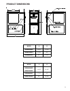
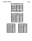
Unit specifications are subject to change without notice. ALWAYS refer to the unit's serial plate for the most up-to-date general and electrical information.
NOTES:
* These furnaces are manufactured for natural gas operation. Optional Kits are available for conversion to propane gas operation.
* For elevations above 2000 ft. the rating should be reduced by 4% for each 1000 ft. above sea level. The furnace must not be derated, orifice changes should only
be made if necessary for altitude.
* The total heat loss from the structure as expressed in TOTAL BTU/HR must be calculated by the manufactures method in accordance with the "A.S.H.R.A.E.
GUIDE" or "MANUAL J-LOAD CALCULATIONS" published by the AIR CONDITIONING CONTRACTORS OF AMERICA. The total heat loss calculated should be
equal to or less than the heating capacity. Output based on D.O.E. test procedures, steady state efficiency times output.
1 Natural Gas BTU/h. For altitudes above 2,000’, reduce input rating 4% for each 1,000’ above sea level.
2 DOE AFUE based upon Isolated Combustion System (ICS)
5 Maximum Overcurrent Protection Device refers to maximum recommended fuse or circuit breaker size. May use fuses or HACR-type circuit breakers of the same size as noted.
Notes:
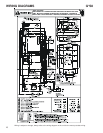
• All furnaces are manufactured for use on 115 VAC, 60 Hz, single-phase electrical supply.
• Gas Service Connection ½” FPT
• Important: Size fuses and wires properly and make electrical connections in accordance with the National Electrical Code and/or all existing local codes.
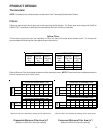
3 Vent and combustion air diameters may vary depending upon vent length.
Refer to the latest editions of the National Fuel Gas Code NFPA 54/ANSI Z223.1 (in the USA) and the Canada National Standard of Canada, CAN/CSA B149.1
and CAN/CSA B142.2 (in Canada).
4 Minimum Circuit Ampacity = (1.25 x Circulator Blower Amps) + ID Blower amps. Wire size should be determined in accordance with National Electrical Codes.
Extensive wire runs will require larger wire sizes.
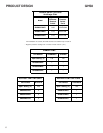
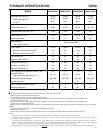
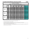
GDS8
MODEL GDS80453AXC* GDS80703AXC* GDS80904BXC* GDS81155CXC*
Btuh Input (US) High Fire
(1)
45,000 70,000 90,000 115,000
Output (US) High Fire
(1)
36,000 56,000 72,000 92,000
A.F.U.E.
(2)
80% 80% 80% 80%
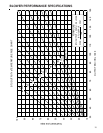
Rated External Static (" w.c.) .20 - .50 .20 - .50 .20 - .50 .20 - .50
Temperature Rise (°F) 35-65 30-60 35-65 40 - 70
Pressure Switch Trip Point (" w.c.) -0.60
-0.70
-0.60
-0.70
Blower Wheel (D" x W") 10 X 6 10 x 6 10 x 8 10 x 10
Blower Horsepower 1/3 1/3 1/2 3/4
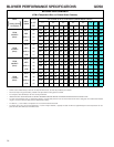
Blower Speeds
Max CFM @ 0.5 E.S.P.
Power Supply 115-60-1 115-60-1 115-60-1 115-60-1
Minimum Circuit Ampacity (MCA)
(4)
8.5 8.5 12.9 12.9
Maximum Overcurrent Device
(5)
15 15 15 15
Transformer (VA) 40 40 40 40
Heat Anticipator (Amps) 0.7 0.7 0.7 0.7
Primary Limit Setting (°F) 220 220 180 180
Auxiliary Limit Setting (°F) 120 120 120 120
Rollout Limit Setting (°F) 300 300 300 300
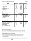
Gas Supply Pressure (Natural/Propane) (" w.c.) 7 / 11 7 / 11 7 / 11 7 / 11
Manifold Pressure
(Natural/Propane) High Stage (" w.c.)
3.5 / 10 3.5 / 10 3.5 /10 3.5 /10
Orifice Size (Natural/Propane) #43 / #55 #43 / #55 #43 / #55 #43 / #55
Number of Burners 2 3 4 5
Vent Connector Diameter (inches)
(3)
4444
Shipping Weight (lbs.) 120 130 153 175
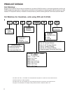
Refer toairflow charts.