


4
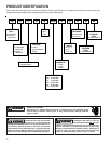
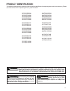
PRODUCT DESIGN
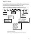
installation (1 or 2 pipes). The optional Combustion Air
Pipe is dependent on installation/code requirements and
must be 2” or 3” diameter PVC.
2. Line voltage wiring can enter through the right or left side
of the furnace. Low voltage wiring can enter through the
right or left side of furnace.
3. Conversion kits for propane gas and high altitude natural
and propane gas operation are available. See High Alti-
tude Derate chart for details.
4. Installer must supply the following gas line fittings, de-
pending on which entrance is used:
Left -- Two 90° Elbows, one close nipple, straight pipe
Right -- Straight pipe to reach gas valve.
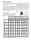
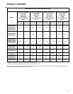
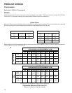
Accessibility Clearances (Minimum)
POSITION* FRONT SIDES REAR TOP FLUE FLOOR
Upflow30010 C
Horizontal Alcove 6 0 4 0 C
*= All positioning is determined as installed unit is viewed from the front.
C= If placed on combustible floor, floor MUST be wood only.
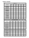
POSITION* FRONT SIDES REAR TOP FLUE FLOOR
Upflow10010NC
Horizontal Alcove 6 0 4 0 C
*= All positioning is determined as installed unit is viewed from the front.
C= If placed on combustible floor, floor MUST be wood only.
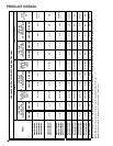
*MVC95* MINIMUM CLEARANCES TO COMBUSTIBLE MATERIALS
(INCHES)
NC= For instalaltion on non-combustible floors only. A combustible
subbase must be used for installations on combustible flooring.
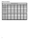
*CVC9 MINIMUM CLEARANCES TO COMBUSTIBLE MATERIALS
(INCHES)
NC= For instalaltion on non-combustible floors only. A combustible
subbase must be used for installations on combustible flooring.
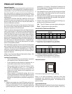
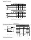
Alcove Illustration
REAR
S
I
D
E
S
I
D
E
A
LCOVE
24" at front is required for servicing or cleaning.
Note: In all cases accessibility clearance shall take
precedence over clearances from the enclosure where
accessibility clearances are greater. All dimensions are
given in inches.
High Altitude Derate
When this furnace is installed at high altitude, the appropri-
ate High Altitude orifice kit must be installed. This is re-
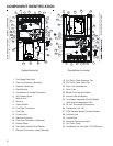
General Operation
Models covered by this manual come with a new 4-wire com-
municating PCB. When paired with a compatible communi-
cating indoor unit and a CTK01AA communicating thermo-
stat, these models can support 4-wire communication pro-
tocol and provide more troubleshooting information. These
models are also backward compatible with the legacy ther-
mostat wiring.
The GCVC9, GCVC95, GMVC95, AMVC95, ACVC9 and
ACVC95 furnaces are equipped with an electronic ignition
device to light the burners and an induced draft blower to
exhaust combustion products.
An interlock switch prevents furnace operation if the blower
door is not in place. Keep the blower access doors in place
except for inspection and maintenance.
These furnaces are also equipped with a self-diagnosing elec-
tronic control module. In the event a furnace component is
not operating properly, the control module's dual 7-segment
LED's will display an alpha-numeric code, depending upon
the problem encountered. These LED's may be viewed
through the observation window in the blower access door.
Refer to the Troubleshooting Chart for further explanation of
the LED codes and Abnormal Operation - Integrated Igni-
tion Control section in the Service Instructions for an expla-
nation of the possible problem.
The rated heating capacity of the furnace should be greater
than or equal to the total heat loss of the area to be heated.
The total heat loss should be calculated by an approved
method or in accordance with “ASHRAE Guide” or “Manual
J-Load Calculations” published by the Air Conditioning Con-
tractors of America.
*Obtain from: American National Standards Institute 1430
Broadway New York, NY 10018
Location Considerations
• The furnace should be as centralized as is practical
with respect to the air distribution system.
• Do not install the furnace directly on carpeting, tile, or
combustible material other than wood flooring.
• When suspending the furnace from rafters or joists,
use 3/8" threaded rod and 2” x 2” x 1/8” angle as
shown in the Installation and Service Instructions. The
length of the rod will depend on the application and
clearance necessary.
• When installed in a residential garage, the furnace
must be positioned so the burners and ignition source
are located not less than 18 inches (457 mm) above
the floor and protected from physical damage by ve-
hicles.
Notes:
1. Installer must supply one or two PVC pipes: one for com-
bustion air (optional) and one for the flue outlet (required).
Vent pipe must be either 2” or 3” in diameter, depending
upon furnace input, number of elbows, length of run and