


g
.
4.
Check the voltage at the compressor motorconnections. Ifthe voltage is 5% below or 10% above
the rated voltage or there is a d'dferencegreater than 3% between phases, shut down the system
and call the power company. A failure to do so may cause damage to the equipment.
After the unit is in operation, itwill take about 30 minutes runningtime to stabilize the system.
In order to check for a properlyworking system, itis recommended that a thermometer be placed
in the-return air and one placed in the air supply. After all insulatingof ductwod_and adjustments
of air registers are complete, a temperature difference of 15° to 20 ° is considered satisfactory.
°
When the above steps are completed, a check of voltage and amperage should be made of all
motors. These readings should be within 10% of the performance ratings given for the specific
ambients.
.
.
Suction and discharge pressures should also be checked to ensure that they agree reasonably well
with the pressures shown in the catalog for the prevailing ambient conditions. Also, a suction
superheat temperature of 20°F (10°F for units with scroll compressors) plus or minus 5° Fis common
for these units when the outdoor ambient is approximately 95°F. This should be used as a gauge in
determining that the system is not overcharged or has lost some of its charge.
Finally, the thermostat should be checked out to assure proper operation. Literature packed with
the thermostat and sub-base will provide informationfor this check out.
HEATING CYCLE CHECK-OUT
1. With the thermostat calling for heat and set at 10° above room temperature, engage disconnect
switch(es) to start the system.
.
All units are factory tested to assure operation of the defrost control system. The clock on the
defrost control is factory set to check for defrost conditions every 60 minutes of unit operation.
The defrost control used in heat pumps has three possibletime settings;30 minutes, 60 minutes,
90 minutes. This clock can be re-set to meet the needs of the area in which the equipment is
installed. In areas where the winter temperatures are low, a 30 minute setting is recommended.
.
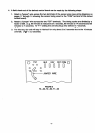
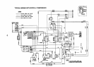
The heat pump is equipped with an electronic defrost control. This solid state defrost control
operates in conjunction with an extemal sensor located at a "cold"spot on the outdoor coil. The
control operates on a "Time/Temp" to initiate and "Temp"to terminate the cycle. The control will
initiatea defrost cycle every 60 minutes (set by the factory) if the coiltemperature at the sensor
is approximately 35"F or less. As the coil is being defrosted, its temperature will rise until it
reaches approximately 65°F. At this point the sensor willterminate the defrost cycle. The entire
process will take between one and three minutes. In areas where the air is generally moisture
laden and frost is prevalent, the defrost interval time may be shortened from 60 minutes to 30
minutes by simply moving the jumper wire (see figure 3) from the "T2" pin to the "1"1". In the
event of a failure of the sensor to open to terminate the defrost, the control has a built-in lr
minute maximum defrost time, after which it will automatically end the defrost cycle.