


22618-4-1106Page 18
INSTALLATION INSTRUCTIONS - GENERAL SAFETY INFORMATION
1. This installation must conform with local codes or, in the ab-
sence of local codes with NFPA54.
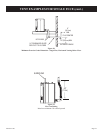
2. Provide adequate clearances around the product for servic
-
ing and ensure there are no obstructions to the combustion
air intake situated at the back of the heater. Refer to Page 15,
Figures 7 and 11.
3. The appliance must be installed on a flat, solid
continuous
surface (i.e. wood, metal, concrete). Please Note: Rough or
uneven surfaces can cause vibration or humming in the heat-
er.
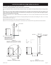
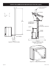
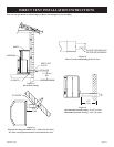
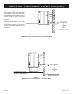
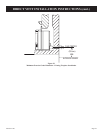
4. The Mantis Power-Vent High-Effeciency Fireplace can be in
-
stalled in a wide variety of ways and will fit nearly any room
layout. It may be installed in a recessed position, framed out
into the room, or across a corner. For installation options re-
fer to page 15.
5. This appliance (Insert and Freestanding Models) needs to be
installed in such a way that the heater can be
removed at all
times to service the heater exchanger and flue fan located in
the rear section of the heater.
Note: Under no circumstances should the appliance be in
-
stalled under conditions which would not allow for
easy removal of the appliance to carry out routine
inspection and service to the appliance, to do so will
void the warranty.
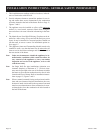
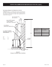
Note: On Single Wall flue pipe installations (imitation zero
clearance fireplace) a minimum of 2” (50.8cm) clear-
ance must be provided at the rear of the heater to enable
the heater to get sufficient combustion air to the air inlet
located at the rear of heater. Refer to installation instruc-
tions on page 15, Figures 7 and 9.
Note: Where a mantel surround is being used on insert installa-
tions and zero clearance fireplace installations, the com-
bustion air intake slot located in the top mantel surround
must have no obstructions to allow combustion air to en-
ter through the slot to the combustion air inlet located at
the back of the heater.