


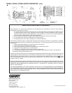
8) Take out the seal case (38) from the valve (if
necessary secure 2 screwdrivers in the front O-ring
groove to extract seal casing from valve casing).
Coat seals with silicon grease before installing.
Mounting surfaces of the crankcase
and the valve casing must be clean and free of
damage. The components must lie exactly and
evenly on one another. The same exactness
applies for all centering positions in the crankcase,
pressure and valve casing.
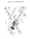
GP8055/GP8060/GP8065 PUMP REPAIR INSTRUCTIONS
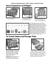
7) Be careful not to damage the seal
sleeve (39) and pressure ring (41). Check the inner
diameter of the pressure ring for wear and if neces-
sary replace together with seals (40) and (42). Clean
all parts. New parts should be lightly coated with
silicon grease before installation. Inert the seal unit
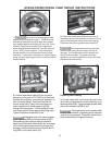
(40, 41, 42 43) into the sleeve. Push the ceramic
plunger carefully through the seals from the crank-
case side. If necessary, the seals can be held tightly
using a suitable pipe support held on the other side of
the seal sleeve.
8) Coat the seal sleeve lightly with anti-corrosive
grease (e.g. molycote no. Cu-7439) in its fitted area
towards the crankcase. Insert the seal sleeves in to
their crankcase fittings. Coat the threads of the
tension screw (36C) lightly with thread glue and
insert it together with a new copper ring (36D)
through the ceramic pipe. Turn the pump per hand
until the plunger (25) rests against the plunger pipe.
Tighten the tension screw at 30 Ft-lbs.
Thread glue must never come between
the plunger pipe (36B) and centering sleeve (36E).
Overtensioning of the plunger pipe by excessive
tightening of the tension screw and/or dirt or damage
on the mounting surfaces can lead to plunger pipe
breakage. Insert the seal tension spring (45) and O-
ring (39A) in to the seal sleeve (39).
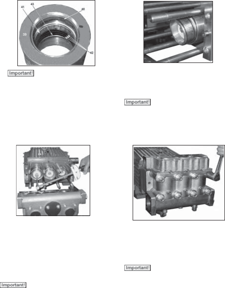
Replacing Valve Casing:
9) Put seal cases (38) in the centering holes of the
valve casing, then push valve casing carefully on to
centering studs (50A). Tighten hexagon screws (49A)
evenly and crosswise at 266 Ft.-lbs.
The torque tension on the screws (49A)
must be checked after 8-10 operating hours; the pump
must be at zero pressure. Thereafter, the tension is
to be checked every 200 operating hours.
10