


9
GP7132 AND GP7136 REPAIR INSTRUCTIONS
CAUTION: Don't loosen the 3 plunger (36) before the valve casing has been removed otherwise the plunger
(36) could hit against the spacer pipe (51F) when the pump is being turned.
Seal life can be increased if the pretensioning allows for a little leakage. This assists lubrication
and keeps the seals cool. It is therefore not necessary to replace seals before the leakage
becomes too heavy and causes output and operating pressure to drop.
MOUNTING VALVE CASING
NOTE: Replace worn parts; grease seals with silicone before installing.
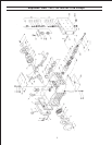
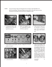
12. Check O-rings (38A) and support rings (38B) on seal case (38). Clean surfaces of seal sleeves in gear box
and sealing surfaces of valve casing. Reassemble seal sleeve (39) by placing plunger (36) in seal sleeve;
place pressure ring (41), v-sleeves (42), sleeve support ring (43), and tension spring (45) over plunger (36).
Place the seal case onto the seal sleeve and press into the crankcase, making sure that the weep hole on
the seal sleeve is facing down. Tighten tensioning screw (36C) for plunger onto crosshead (25) with an
open end wrench to 26 ft-lbs.
13. Push valve casing carefully onto O-rings of seal case and centering studs (50A). Tighten nuts (49A) to103
ft-lbs.
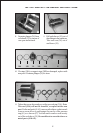
TO DISASSEMBLE GEAR
14. Take out plunger (36) and seal sleeves (39) as described above. Drain oil.
15. After removing the circlip ring (33B), lever out seal retainer (33) with a screw driver. Check seals
(32,32A,33A) and surfaces of crosshead.
16. Remove crankcase cover (4). Loosen inner hexagon screws on the connecting rods (24) and push con rod
halves as far into the crosshead guide as possible.
CAUTION: Connecting rods are marked for identification. Do not twist con rod halves. Con Rod is to be
reinstalled in the same position on shaft journals.
17. Check surfaces of connecting rod and crankshaft (22). Take out bearing cover (14) to one side and push
out crankshaft taking particular care that the connecting rod (24) doesn't bend.
CAUTION: Seal (32A) must always be installed so that the seal-lip on the inside diameter faces the oil.
Reassemble in reverse order: Regulate axial bearing clearance - minimum 0.1mm, maximum
0.15mm-by means of fitting disc (20A). The crankshaft (22) should turn easily with little
clearance. Tighten fitting screws (24A) to 30 ft.-lbs.
CAUTION: Connecting rod (24) has to be able to be slightly moved sidewise at the stroke journals.
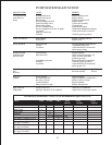
GP7132 and GP7136 TORQUE SPECIFICATIONS
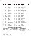
Position Item# Description Torque Amount
24A 07616 Fitting Screw 30 ft-lbs.
36C 07664 Tensioning Screw 26 ft.-lbs.
49A 13160 N u t 103 ft.-lbs.
58 07699 Plug 155 ft.-lbs.