


6
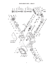
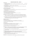
REPAIR INSTRUCTION - GP6132
To Check Valves
1. Loosen plugs (56) and take out complete valve assemblies (51) with a slide hammer. Use a bent piece of wire
to remove the o-rings (52).
2. To dismantle the valves, carefully tap the valve plate (51B) with a bolt until the valve seat (51A) is pushed out of the
spacer pipe (51D).
3. Check the sealing surfaces and replace all worn parts. Check the o-rings.
4. When reinstalling the valve assemblies, particular care must be taken so that the o-rings (52) sit properly in their
fittings in the valve casing.
5. Tighten the plugs (56) to 160 ft.-lbs. (220 NM).
To Check Seals and Plunger Pipe
6. Loosen nuts (49A) and remove the valve casing (50).
7. Separate the plunger connection (36) from the crosshead assembly (25) by means of two open-end wrenches (size
22mm and 27mm).
8. Pull seal sleeves (40) out of their fittings in the crankcase (1).
9. Take the seal case (41) out of the seal sleeve (40).
10. Examine plunger parts (36-39) and seals (44 and 45).
11. Check o-rings (41A through 41D) and replace worn parts.
12. When replacing plunger pipe (37), tighten tension screw (38) to 30 ft.-lbs (40 NM).
13. Grease seals with Silicone before reinstalling.
IMPORTANT: Do not loosen the three plunger screws (36) before the valve casing (50) has been removed;
otherwise, the tension screw (38) could hit against the spacer pipe (51D) when the pump is being turned.
14. The seal unit (43, 44, 44A) is pre-tensioned by a spring (42). Seal life can be increased if the loading allows for a
little leakage. This assists lubrication and keeps the seals cool. It is therefore not necessary to replace the seals
before the leakage becomes too heavy and causes output and operating pressure to drop.
15. When reassembling, tighten plunger screw (36) to 33 ft.-lbs. (45 NM).
Mounting Valve Casing
16. Check o-rings on seal case (41).
17. Clean surfaces of seal sleeves in crankcase (1) and sealing surfaces of valve casing (50).
18. Push valve casing (50) carefully onto o-rings (41A and 41B) of seal case and centering studs (49C).
19. Tighten nuts (49A) to 103 ft.-lbs. (140 NM).
To Dismantle Gear
20. As described above, take out the plunger and seal sleeves. Drain the oil.
21. After removing the circlip ring (33B), use a screw driver to lever out the seal retainer (33).
22. Check the seals (32, 32A and 33A) and surfaces of the crosshead (25).
23. Remove the crankcase cover (4) and make sure that the o-ring (5) looks good.
24. Loosen the inner hexagon screws on the connecting rods (24).
IMPORTANT: Connecting rods are marked for identification. Do not twist connecting rod halves. Connecting
rod halves are to be reinstalled in the same position and orientation onto the crankshaft (22).
25. Push the connecting rod halves as far into the crosshead guide as possible.
26. Take out the bearing cover (14) to one side and push out the crankshaft (22) taking particular care that the connecting
rod halves don’t bend
IMPORTANT: Seal (32A) must always be installed so that the seal lip on the inside diameter faces the oil. Pos-
sible axial float of the seal adaptor (33) is to be compensated for with shims (33C).
27. Reassemble in reverse order
28. Regulate axial play of the crankshaft clearance to minimum of 0.1mm, maximum of 0.15mm by means of fitting disc
(20A). The crankshaft should turn easily and with little clearance.
29. Tighten the inner hexagon screws to 30 ft-lbs. (40 NM).
IMPORTANT: The connecting rods have to be able to slightly moved sidewise at the stroke journals.