F
or H
elp
,
c
all 1-800-35-GENIE or visit www
.geniecompany.com
5
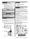
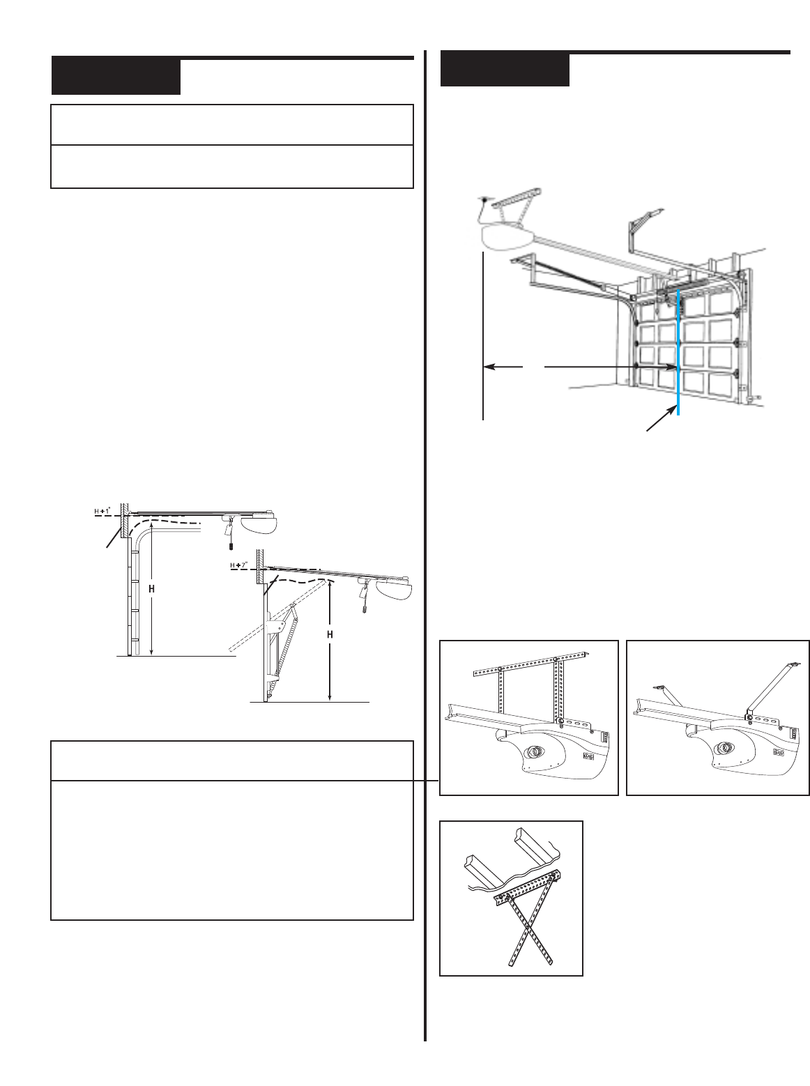
• Mark a point at center of door and on header directly
above door. Draw a center line to connect points.
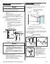
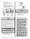
B Find Header Bracket mounting height (Figure 4): (Do not attach
Header Bracket).
• Raise door,watching top edge of door and stop door
when its edge reaches its highest point.
• Measure distance (“H”) from top edge of door to floor.
– For sectional doors, add 1" to “H”. Mark a point
on center line. Bottom of Header Bracket will be
installed here.
– For one-piece doors,add 7" to “H”. Mark this point on
center line. Bottom of Header Bracket will be
installed here.
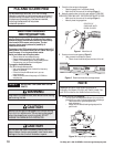
C Check wall for a stud or a solid header at your mark: (If checking a
finished wall, a stud finder may be helpful).
• If location is above Header, a 2" x 6" board must be
screwed to studs beside your mark with at least two Lag
Screws and Flat Washers (not provided).
• T
r
ansf
er y
our mar
k t
o new moun
ting b
oard.
NOTE
• For both types of doors:
– If the ceiling in your garage is so low that there
is not at least a 3" space above the Header
Bracket mounting point,contact a Genie Factory
Authorized Dealer.
• If a door spring is in the way, place the Header
Bracket above the spring.
Do Not move the door
spring.
Figure 4 Find Highest Point of Travel
SECTIONAL DOOR
ONE-PIECE DOOR
HEADER
HEADER
CHECK DOOR HEADER AREA
A Find vertical center line of door and header:
• Close door.
• Measure door width at top.
Check Step 4:
NOTE
The header is a heavily reinforced section of the wall just
above the top of the garage door opening.
CHECK POWER HEAD
MOUNTING AREA
C
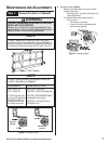
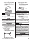
heck ceiling or space above where Opener Power Head will be
mounted (
Figure 5):
A Measure from garage door center line toward rear of garage:
• Approximately 11'.
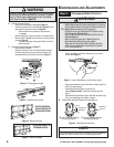
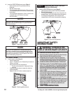
B Find location of ceiling joist or truss above where Opener Power
Head will be and estimate type and quantity of materials needed for
your installation (Figure 6).
Check Step 5:
120 Volt grounded outlet
or wiring box within 3 feet of
Power Head.
Door Center Line
Figure 5 Check Power Head location
11'
Conduit
Perforated Angle Iron
F
igur
e 6
M
oun
ting metho
ds f
or op
en b
eam or finished c
eilings
FINISHED CEILINGS
Locate ceiling joists or trusses using
a stud finder or similar device.
Attach angle iron(not included) to
joists or trusses through finish
material using Lag Screws.
OPEN CEILINGS Straps and angle
iron may attach directly to joists
or trusses.
MOUNTING EXAMPLES
55 11
30
30
55 11
30
P
erforated Straps


