


6
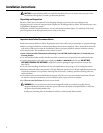
Installation instructions.
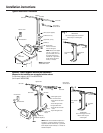
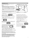
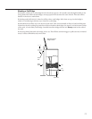
Typical Installation Illustration
Optional 3-Valve Bypass Installation Illustration
Soft water
Hard water to
outside faucets
MAIN WATER PIPE
Hard water
NOTE:
See
Drain Hose
Connections
section.
24V transformer
120-volt outlet
Hard water
Soft water
From softener
outlet
To softener
inlet
Hard water
Soft water
From softener
outlet
To softener
inlet
CROSS-OVER
Use if water supply flows from the left.
Include single or 3-valve bypass.
MAIN WATER PIPE
Soft water
Hard water
24V transformer
120-volt outlet
Bypass valve
Hard water to
outside faucets
Inlet valve
Outlet valve
3-valve bypass system
For soft water service:
• Open the inlet and outlet
valves
• Close the bypass valve
For bypass hard water:
• Close the inlet and outlet
valves
• Open the bypass valve
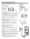
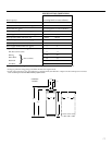
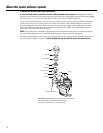
SALT
GOES HERE
Brinewell
INLET
Washer (2)
Copper tube, 3/4″ (2)
Installation nut (2)
Bypass Valve
• Pull out for service
• Push in for bypass
NOTE:
Threads on the bypass
valve are 1″ male pipe. If 1″
pipes are needed, do not use
the copper tubes and nuts
included. Buy 1″ pipe thread
female adapter, and plumb
directly to 1″ threads.
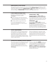
Adapters for this installation are not supplied with the softener.
To order these adapters, call GE Parts 800-626-2000.
(Ask for part # WS60X10006)
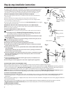
Nut (2)
Copper tube,
3/4″ (2)
Washer (2)
Installation adapter (2)
INLET
NOTE:
Threads on the installation adapters are 1″
male pipe. If 1″ pipes are needed, do not use the
copper tubes and nuts included. Buy 1″ pipe thread
female adapter and plumb directly to 1″ threads on
installation adapters.
CROSS-OVER
Use if water supply flows from
the left. Include single or
3-valve bypass.
Fig. 1
Fig. 2
Union (2) (not supplied)