


6
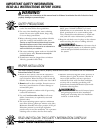
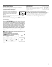
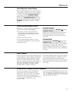
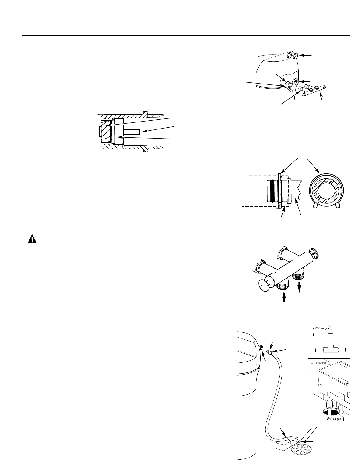
Fig. 3A
Fig. 3B
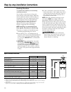
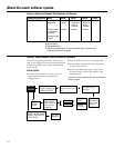
Fig. 3C
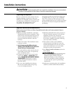
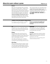
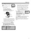
Fig. 4
Drain
fitting
on valve
Valve drain hose
FLOOR DRAIN
IN
OUT
Turn bypass valve
upside down to
connect to floor
level plumbing
Valve body
inlet or outlet
Bypass valve
(push all the way in)
Clip
END
VIEW
Clip
Outlet
Inlet
O-ring seal goes into
the outer groove only.
The clip snaps into the
inner groove (see below).
Bypass
valve
SIDE
VIEW
Tie or wire
hose in place
1
1
⁄2″ air gap
LAUNDRY TUB
SUMP
Clamp
Step-by-step installation instructions.
■ Turn off the gas or electric supply to the water heater, in the possibility that the water
heater may be drained while draining pipes.
■ Turn off the water supply to pipes to be cut and drain the house water pipes.
■ Open both hot and cold faucets at the lowest location possible.
NOTE: For easier installation, remove the top cover. Release 2 clips at rear of the cover.
Rotate cover forward and lift up.
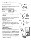
1. INSTALL BYPASS VALVE
• Remove plastic shipping plug and wire from valve outlet.
• Push the bypass valve (lubricate o-ring seals with silicone grease) into both ports of
the valve as shown in Fig. 3A.
• Snap the 2 large plastic clips in place, from the top, down as shown in Figures 3A
and 3B. Be sure they snap into place. Pull on the bypass valve to make sure it is held
securely in place.
2. MOVE THE SOFTENER ASSEMBLY INTO INSTALLATION POSITION
Be sure the installation surface is level and smooth. Sharp objects under the tank may
puncture it. If needed, place the tank on a section of 3/4″ thick (minimum) plywood.
Then, place shims under the plywood as needed to level the softener.
3. PLUMB “IN” AND “OUT” PIPES TO AND FROM SOFTENER
CAUTION: Observe all of the following cautions as you connect inlet and
outlet plumbing. See illustrations on page 5.
• BE SURE INCOMING HARD WATER SUPPLY IS DIRECTED TO THE
SOFTENER VALVE INLET PORT. If house water flow is from the left, use a
plumbing crossover as shown in Fig. 1, page 5. If house water flows up from the
floor level, turn the bypass valve upside down as shown in Fig. 3C.
• If making a soldered copper installation, do all sweat soldering before connecting
pipes to the bypass valve. Torch heat will damage plastic parts.
• When turning threaded pipe fittings onto plastic fittings, use care not to
cross-thread.
• Use pipe joint compound on all external pipe threads.
• Support inlet and outlet plumbing in some manner (use pipe hangers) to keep the
weight off of the valve fittings.
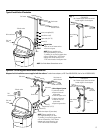
4. CONNECT AND RUN THE VALVE DRAIN HOSE
• Use the provided drain hose (20′ length included) to attach to the valve drain
fitting. To keep water pressure from blowing the hose off, use a hose clamp to secure
in place. Cut the necessary length and use the remainder in Step 5.
• Locate the other end of the hose at a suitable drain point (floor drain, sump,
laundry tub, etc.) that terminates at the sewer. Check and comply with local codes.
IMPORTANT: If more drain hose is needed, it should be ordered from GE Parts at
800.626.2002. The water softener will not work if water cannot exit this hose during
recharge.
• Tie or wire the hose in place at the drain point. High water pressure will cause it to
whip during the back-wash and fast rinse cycles of recharge. Also provide an air gap
of at least 1
1
⁄2″ between the end of the hose and the drain point. An air gap prevents
possible siphoning of sewer water into the softener, if the sewer should “back-up.”
• If raising the drain hose overhead is required to get to the drain point, do not raise
higher than 8′ above the floor. Elevating the hose may cause a back-pressure that
could reduce brine draw during recharge.
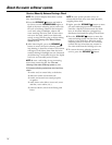
STANDPIPE
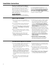
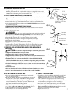
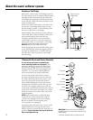
NOTE: Be sure the turbine and
support are firmly in place in the
valve outlet. Blow into the valve
port and observe the turbine
for free rotation.
Turbine
Valve outlet
Turbine shaft
and support
Drain
Fitting