


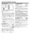
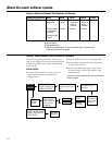

1. To enter diagnostics, press and hold the
MODE button until (000 – –) shows in the
display.
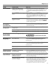
A The first 3 digits indicate water meter
operation as follows:
■ 000 (steady) = soft water not in
use…no flow through the meter.
—OPEN A NEARBY SOFT WATER FAUCET—
■ 000 to 199 (continual) = repeats display for each
gallon of water passing through the meter.
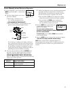
If you don’t get a reading in the display, with faucet
open, pull the sensor from the valve outlet port. Pass
a small magnet back and forth in front of the sensor.
You should get a reading in the display. If you get a
reading, shut off water supply, unhook the in and out
plumbing and check the turbine for binding.
B The letter (P) and dash(es) indicate POSITION switch
operation. The letter appearing means the switch is
closed; the dash means the switch is open. Use the
RECHARGE (RECHARGE TONIGHT–RECHARGE NOW)
button to manually advance the valve into each cycle and
check correct switch operation.
C While in this diagnostic screen, the following information
is available and may be beneficial for various reasons.
This information is retained by the computer from the
first time electrical power is applied to the control.
■ Press and hold the UP button to display the number
of days this control has had electrical power applied.
■ Press and hold the DOWN button to display the
number of regenerations initiated by this control
since the SR code number was entered.
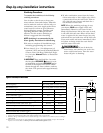
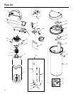
2. Press the MODE button and hold in three
seconds until a Service Rating code
appears in the display.
For correct water softening system
operation, the model code must be SR22 for model GXSF27E
and F31 for model GXSF31E.
To reset the code, press the UP or DOWN button until the
correct number shows.
3. Press the MODE button to return to the present time display.
If the code was changed, make ALL the timer settings.
NOTE: If the control is left in a diagnostic display or a
flashing display when setting times or hardness, present time
automatically returns if a button is not pressed within four
minutes.
15
GEAppliances.com
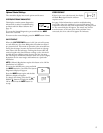
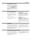
CORRECT SWITCH
DISPLAYS VALVE CYCLE STATUS
— — Valve in service, fill, brining, backwash
or fast rinse position.
— P Valve rotating from one position to another
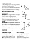
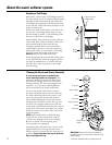
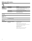
Turbine Switches
Water
Meter (A)
Switch (B)
OR
Service: Manually Initiated Electronics Diagnostics
Motor
Turbine
Turbine support
and shaft
Sensor
housing
Position
switch
Valve
outlet