


9
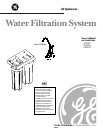
Step-by-step installation instructions.
Customer Service
Troubleshooting Tips
Operating InstructionsSafety Instructions Installation Instructions
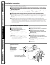
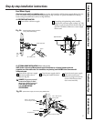
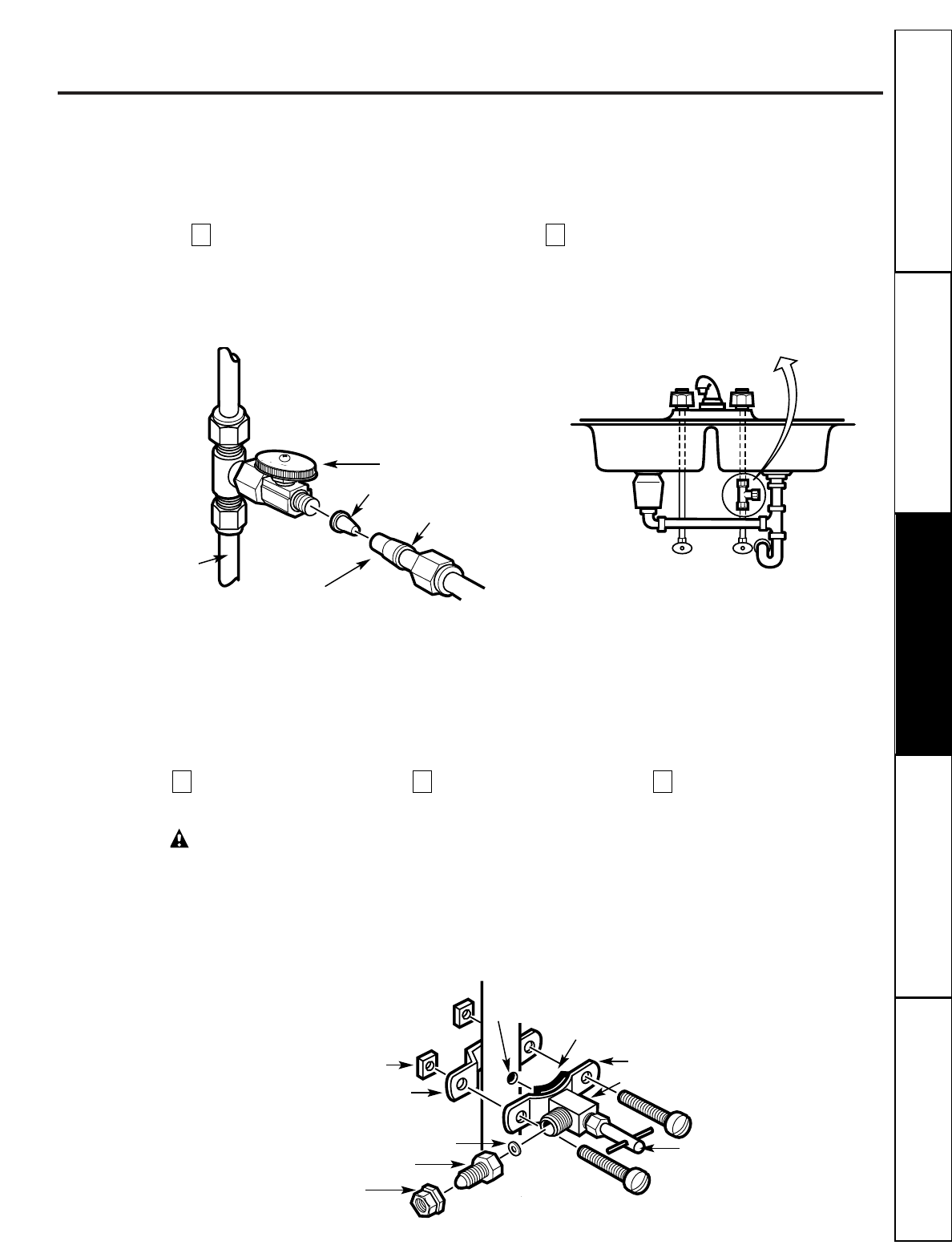
Feed Water Supply
Check and comply with local plumbing codes
as you plan, then install a cold feed water supply fitting. For new
home installation using standard plumbing fittings, see Fig. 2A below. A typical installation for existing
homes using the saddle valve is shown in Fig. 2B below.
A. PREFERRED INSTALLATION
B. OPTIONAL HOME INSTALLATION Where codes permit
NOTE: Codes in the state of Massachusetts require installation by a licensed plumber and do not
permit the use of the saddle valve. For installation, use plumbing code 248-CMR of the Commonwealth
of Massachusetts.
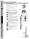
Optional water supply connection (using saddle valve)
Pre-drill
1⁄4″ hole
Seal—make sure the
seal is in place
Clamp X
Nut (2)—not required if
holes in clamp are threaded
Valve
Handle
Tubing adapter
Washer
Compression nut
❵
Clamp Z
Fig. 2B.
Turn off the cold water supply
and attach saddle valve as
shown in Fig. 2B.
DANGER:
To protect yourself
from serious injury or fatal
shock, use a battery powered
hand drill only to make the
hole.
DO NOT USE AN
ELECTRIC DRILL.
Close the water supply valve by
turning the handle clockwise.
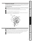
Open the main water supply
valve and several house
faucets to purge air from the
system. Close faucets when
water runs smoothly.
321
Turn off the cold water supply.
Complying with plumbing codes, install a
fitting on the cold water pipe to adapt 3⁄ 8″ OD
tubing. A typical connection is shown in Fig. 2A
(parts not included). Make sure a water supply
valve is used.
21
Fig. 2A.
Preferred water supply connection
(using compression fitting)
Insert
Cold
water
pipe
3⁄8″ tubing to inlet
Ferrule
Water supply valve
Typical location
Cold
water
Use to connect the tubing