


Installation Instructions
7
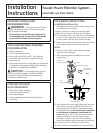
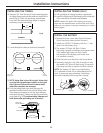
COLD WATER SUPPLY FITTING (CONT.)
B. OPTIONAL HOME INSTALLATION
(Where codes permit)
Saddle Valve: Saddle valve must be able to
connect with 1/4-inch tubing supplied with the
system. Not supplied with product; check your
local hardware or home service store for
product. Saddle valve typically requires 1/2″
OD tubing or larger.
NOTE: Codes in the state of Massachusetts
require installation by a licensed plumber and
do not permit the use of the saddle valve. For
installation, use plumbing code 248-CMR of the
Commonwealth of Massachusetts.
1. Turn off the cold water supply and install saddle
valve as required by product selection. (Be sure to
follow manufacturer’s installation instructions.)
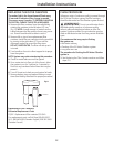
DANGER —
If hole is required to be drilled
in pipe, to protect yourself from serious injury or
fatal shock, use a battery-powered hand drill only
to make the hole. DO NOT USE AN ELECTRIC DRILL.
2. Open saddle valve after complete system has
been installed.
C. OPTIONAL INSTALLATION
(For installation with rigid pipe between supply
valve and sink faucet)
Option 1
1. Remove pipe from supply valve and sink faucet.
2. Obtain flexible pipe sized to your plumbing.
3. Install flexible pipe.
4. Go back to A. Preferred Installation section
step 3.
Option 2
1. Obtain compression fittings to fit rigid pipe.
2. Obtain any other fittings required to connect
compression fittings to feed water adapter.
3. Remove pipe from supply valve.
4. Cut pipe to fit length of assembled fittings and
adapter.
5. Install compression fitting to pipe.
6. Go back to A. Preferred Installation section
step 3.
NOTE: Above described materials are not
included with the product.
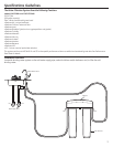
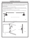
INSTALL THE FAUCET
Be sure there is room underneath and above
the sink to make the needed connections. Before
starting, make sure there is sufficient room for the
faucet base and unit. Select one of the following
places to install the faucet:
A. In an existing sink spray attachment or soap
dispenser hole.
B. In a hole to be drilled in the sink top.
C. In a hole to be drilled in the countertop, next
to the sink.
NOTES:
• Be sure the faucet base will fit flat against the
surface at the selected location so the bottom
gasket between the base and surface area
will seal.
• Make sure to leave enough clearance at the back
of the faucet in case you need to remove it.
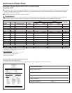
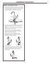
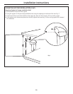
Installation Steps (refer to illustration below
for clarification)
1. If drilling is needed, make a 1″ diameter hole.
Be sure to use the proper procedure for drilling
porcelain or stainless steel. Special drill bits
may be needed. Consult a qualified plumber
for the proper procedure.
CAUTION: When drilling in Stainless
Steel, the edges may be sharp and could puncture
the tube. Be careful to not cut yourself or damage
the tube.
2. Remove the faucet body and base by turning
the base counterclockwise.
3. Remove the butterfly bracket from the screw.
Then insert the screw into the top of the base
and reattach the butterfly bracket.
4. Align the gasket to cover the hole completely.
Then place the butterfly bracket on the base
into the hole.
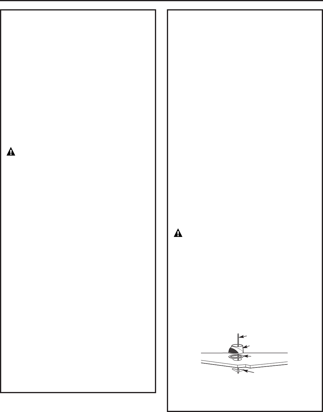
5. Tighten the screw to secure the butterfly bracket
to the underside of the sink top. The base should
be firmly in place and should not wobble or turn.
Base
Sink
Gasket
Butterfly Bracket
Screw