10
Installation Instructions
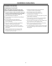
CORROSIVE ATMOSPHERES
NOTICE: The water heater or intake air supply
should not be installed near an air supply
containing halogenated hydrocarbons
or near swimming pool chemicals.
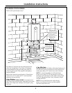
MOUNTING THE WATER HEATER
CAUTION: Reinforcement of the
wall is required in case the wall is not strong
enough to hold the water heater. Do not mount
to drywall unless mounting screws are secured
in wall studs.
Make sure the location of the water heater allows
for easy access and operation.
Wall studs should be utilized when mounting the
water heater to the wall. On masonry or concrete
wall, use concrete anchors or lag bolts.
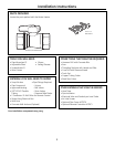
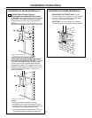
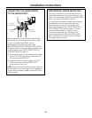
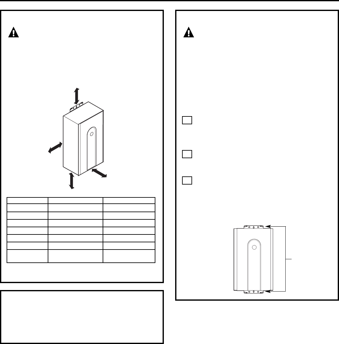
Identify the installation location and confirm
that the installation will meet all required
clearances. Use mounting template
to locate screw and anchor locations.
Securely attach the water heater to the wall
using the brackets located at the top and
bottom of the water heater.
Ensure that the attachment strength is
sufficient to support the weight. Refer to the
weight of the water heater in the Specification
Guidelines. Four mounting screws with 200 lb.
tensile load capability are required at
a minimum.
3
2
1
Wall installation
brackets
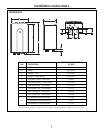
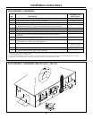
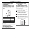
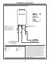
CLEARANCES FOR WATER HEATER
WARNING: Combustible
construction refers to adjacent walls and ceiling
and should not be confused with combustible or
flammable products and materials. Combustible
and/or flammable products and materials should
never be stored in the vicinity of this or any gas
appliance.
To front
To top
To side
To floor/ground
*Every vent connection must be accessible for inspection, cleaning
and replacement.
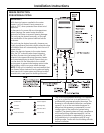
To combustibles To noncombustibles
Top of heater 6 inches (152 mm) 2 inches (51 mm)
Back of heater 0 (zero) 0 (zero)
Front of heater 6 inches (152 mm) 6 inches (152 mm)
Sides of heater 2 inches (51 mm) 1/8 inch (3 mm)
Floor/ground 12 inches (305 mm) 12 inches (305 mm)
Vent 0 (zero) 0 (zero)
Closet 6 inches (152 mm) 6 inches (152 mm)
from front from front


