


5Indoor/Outdoor PIR Motion Sensors Installation Instructions
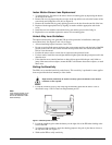
Outdoor Motion
Sensor
Mounting
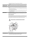
1. Determine the desired mounting location for the sensor leaving at least four inches of room
above the wall mount plate to attach the sensor.
2. Using the screws and anchors supplied, attach the wall mount plate with the opening for the
swivel mount facing downward.
3. Attach the sensor assembly to the wall mount plate by screwing the sensor assembly up into
the opening in the wall mount plate.
4. To remove the sensor for testing or battery replacement, slide the front cover of the sensor
upward until the sensor can be removed.
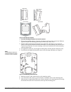
Filter Installation
A one inch by one inch piece of lens material has been included with the outdoor motion sensor.
The filter reduces the sensors sensitivity to white light sources (sunlight and head lights) and
infrared sources. Install the filter when experiencing unwanted sensor activations due to these
sources.
1. Remove the sensor from its water resistant enclosure by sliding the front cover upward until
the sensor can be removed.
2. Remove the mounting plate of the sensor by depressing the button on top of the sensor.
3. Remove the front cover of the sensor by depressing the two tabs on the top and the one tab on
the bottom of the sensor body and sliding the cover off (see Figure 8)
4. Place the sensor on its back and drop the filter into the lens chamber covering the sensor’s
detector.
5. Replace the cover, making sure the filter remains in the lens chamber and does not interfere
with the attachment of the cover.
6. Replace the sensor’s mounting plate and install the sensor in its water resistant enclosure.
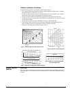
Testing Walk Testing
Walk testing should be done to determine the sensor’s actual coverage area. The edge of the cov-
erage pattern is determined by the first flash of the LED. This may change slightly depending
upon the sensitivity setting. Walk test the unit from both directions to determine the pattern
boundaries.
1. Remove the sensor body from the mounted mounting plate, activate the tamper switch, and
remount the body to activate the 60 second walk test mode.
2. Walk across the coverage pattern to determine the coverage area, indicated by LED activation.
Each activation extends the walk test mode for an additional 60 seconds.
After 60 seconds without motion the walk test mode and the LED will no longer activate when
motion is detected.
Note
When the walk test mode
has ended, an alarm can be
transmitted only after 3 min-
utes have passed since the
previous alarm. This 3
minute lockout time reduces
unnecessary RF transmis-
sions in high traffic areas
thereby extending battery
life.
Environment Testing
Indoor Motion Sensors
Turn on all heating or air conditioning sources which would normally be active during the protec-
tion period. Stand away from the sensor and outside the coverage pattern and watch for alarms.
Outdoor Motion Sensors
Verify that the sensor’s coverage area does not extend into undesired areas that might cause
unwanted activations. These areas may include undesired human, pet, or automobile motion.
Coverage
Masking
After walk testing and environment testing are completed, masking labels can be applied to the
sensor’s lens to block detection of problem areas. The masking labels provided are cut to match
the corresponding lens segments.
Excessive use of the walk test mode may reduce battery life. Use only for initial
setup and maintenance testing.
Caution
!