19
SERVICING INSTRUCTIONS
REPLACING PARTS
6.6 Check all joints for gas leaks. Check the operation of the
thermocouple and ignition lead.
7. MAGNETIC SAFETY VALVE
7.1 Turn the gas supply off at the isolation device. Undo the
thermocouple connection from the back of the gas valve.
Pull the sensor leads clear and remove the interrupter block.
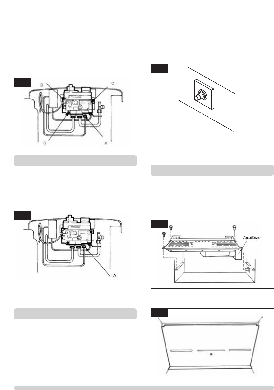
7.2 Undo the mag valve retaining nut at the back of the control
valve. Gently tap out the mag valve and replace with a new
unit. Replace the retaining nut and tighten. See diagram 11,
Arrow A.
7.3 Reassemble the interrupter block and leads. Secure the
thermocouple connection in the rear of the gas control (Do
not overtighten). Turn the gas supply on and check the
entire pipework and valve joints for any leaks.
8. MAIN INJECTOR
8.1 Turn the gas supply off at the isolation device. Refer to
Section 2, Replacing Parts to remove the main burner.
8.2 Undo the compression nut from the feed pipe at the gas
control under the appliance.
8.3 Working from inside the firebox, remove the lock nut from
the injector, see diagram 12 and withdraw the injector
complete with the feed pipe from under the appliance. See
diagram 12.
8.4 Holding the injector with a spanner, undo the feed pipe.
NOTE: THE ORIENTATION OF THE INJECTOR.
8.5 Reassemble in reverse order. Turn on the gas supply and
check for any leaks.
9. GAZCO FLUE SURE SYSTEM
9.1 Remove the front door by undoing the four dome nuts and
remove the cast iron door. NOTE: THE CAST IRON DOOR
IS HEAVY. TAKE EXTREME CARE WHEN HANDLING.
Carefully remove the coal retainer and ceramic components
and place to one side. Remove the burner casting by
removing the three screws located on the sides of the burner
skin.
9.2 Remove the screw on the back panel and remove the panel.
Refer to Diagram 14.
AR0943b
10
AR0618
12
AR0943c
11
AR1605
13
AR1606
14


