


17
SERVICING INSTRUCTIONS
REPLACING PARTS
1. GENERAL
1.1 All principal components can be replaced without removing
the stove from its installation, although it is essential that the
gas supply to the appliance is turned off at the isolation
device before proceeding further.
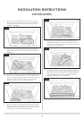
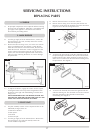
2. MAIN BURNER
2.1 Turn the gas supply off at the isolation device, remove the
door and place to one side, carefully remove the ceramic
fuel bed components.
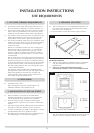
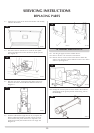
2.2 Remove the three securing screws, two at the rear and one
at the front left-hand side. See diagram 1. Raise the left-
hand side of the burner to clear the bracket, draw the left-
hand side forward. The burner venturi is engaged over the
injector. When removing the burner be sure to clear the
injector, this will release the right-hand side of the burner.
Take care when removing the burner so as not to damage
the pilot burner.
2.3 To replace the burner, engage the venturi over the injector
ensuring the burner sits on top of the fixing bracket. Push
the burner to the right and whilst holding, insert the three
fixing screws.
NOTE: BEFORE REPLACING THE BURNER, ENSURE THE
SILICONE SEAL AROUND THE INJECTOR IS INTACT AND
CHECK THAT VENTURI COVER IS ATTACHED.
3. PILOT UNIT
3.1 The pilot assembly consists of four components that can be
individually changed, these are:
1) Pilot burner bracket
2) Pilot injector
3) Electrode
4) Thermocouple
3.2 Turn the gas supply off at the isolation device. Remove the
door and place to one side and carefully remove the
ceramic fuelbed components.
AR1605
1
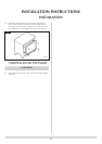
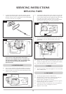
3.3 Remove the main burner. See Section 2 above.
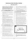
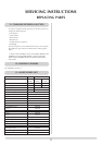
3.4 Remove the two fixing screws from the pilot bracket. See
Diagram 2. Gently draw the assembly away from the firebox
to give access to the nuts and ignition lead.
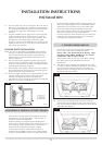
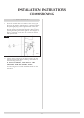
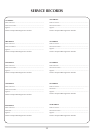
3.5 To remove the pilot injector, undo the compression nut on
the pilot feed pipe and withdraw the injector which will be
hooked onto the olive. When replacing an injector always
make sure it is hooked onto the olive before inserting it into
the pilot burner. See diagram 3.
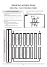
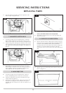
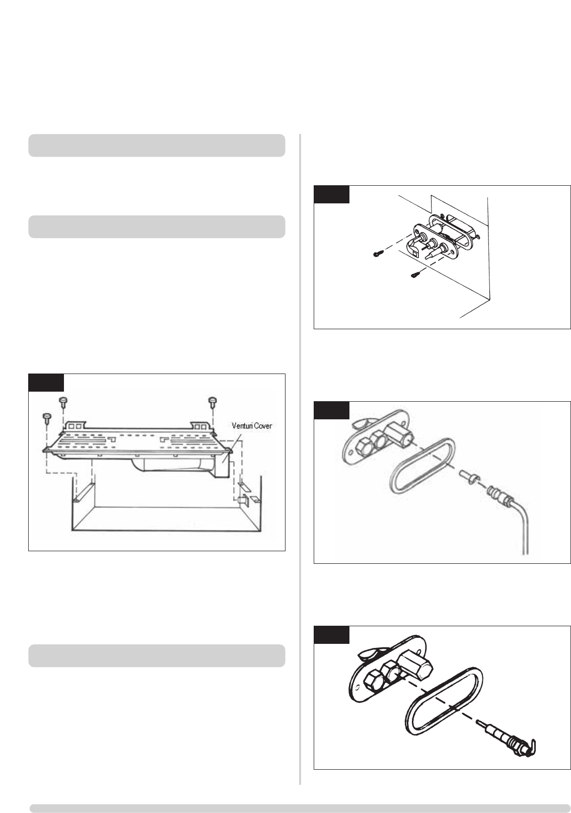
3.6 To remove the electrode, disconnect the ignition lead and
undo the retaining nut. The electrode can now be removed.
Note the orientation of the electrode terminal when
reassembling. See diagram 4.
AR0614
2
AR0616
4
AR1604
3