


18
SERVICING INSTRUCTIONS
REPLACING PARTS
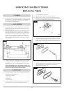
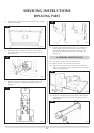
3.7 To remove the thermocouple, undo the retaining nut and
withdraw the thermocouple. Undo the thermocouple from
the back of the gas valve. See Diagrams 5 and 6. Reassemble
in reverse order. Do not overtighten.
NOTE: Special care should be taken when replacing the
thermocouple to the back of the gas valve ensuring that the
sensor wires for the gazco flue sure system are not
disconnected.
4. IGNITION LEAD
4.1 Gain access to the back of the pilot assembly, see Section 3
above and disconnect the ignition lead from the electrode.
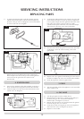
4.2 Undo the single screw that secures the left-hand side of the
control cover, see Diagram 7.
4.3 To release the right-hand side of the control cover insert the
narrow blade screwdriver into the slot shown in diagram 8.
Lever it gently and pull from the right-hand side at the same
time. The cover will now come off. There is a small
cylindrical metal spacer inside the cover; this must be kept
and replaced on the fixing screw during reassembly.
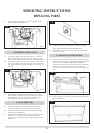
4.4 Disconnect the end of the ignition lead from the valve body,
see diagram 9, Arrow B, note the existing route of the
ignition lead.
4.5 Replace with a new ignition lead following the same route as
the old one. Replace the valve cover and the pilot assembly.
4.6 Check the operation of the new ignition lead.
5. PIEZO
5.1 The piezo assembly used on this appliance is not serviceable
and is unlikely to fail.
6. GAS VALVE
6.1 Turn the gas supply off at the isolation device.
6.2 Disconnect the 2 x 8mm and 1 x 4mm gas pipe fittings at
the back of the gas valve and also disconnect the
thermocouple, see Diagram 10, Arrow A.
6.3 Remove the control valve cover and disconnect the ignition
lead from the gas valve, see section 4.
6.4 Undo the two bolts securing the gas valve to the appliance
and remove the valve, see diagram 10, Arrow C
6.5 Replace in reverse order.
AR0617
5
AR0943c
6
AR0915
7
AR0916
8
AR0943a
9