


15
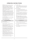
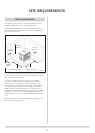
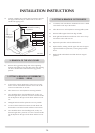
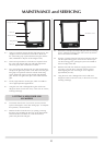
1.4 Lift the stove into position on the prepared hearth area,
taking care not to damage the hearth finish. Level stove
using foot adjusting bolts.
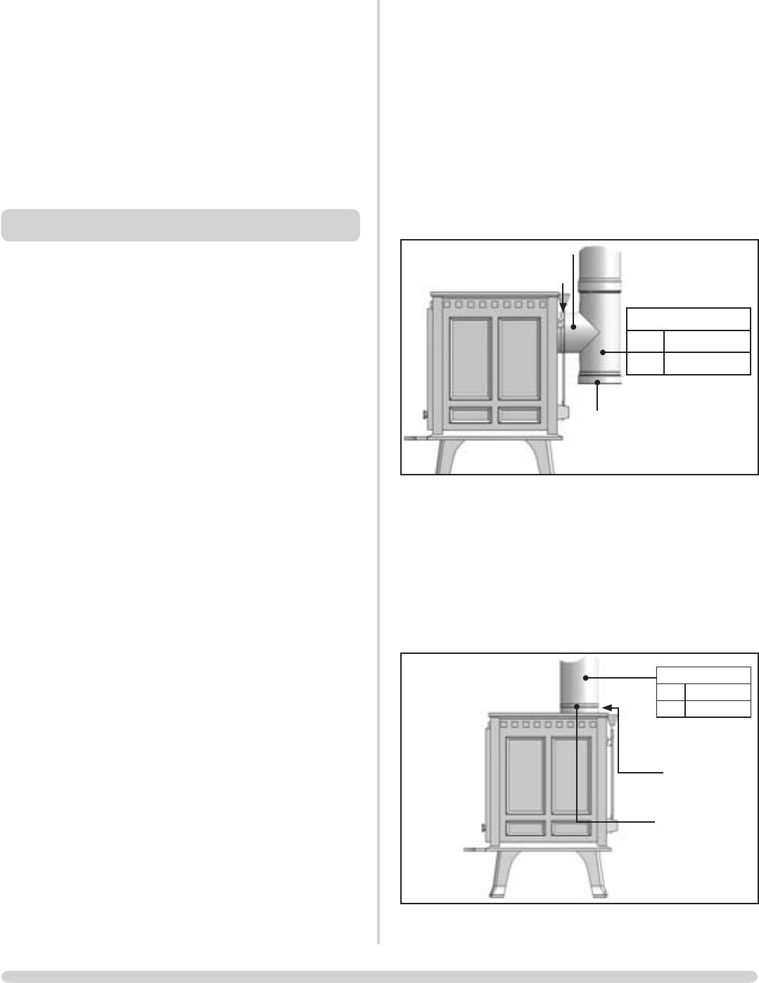
1.5 Connect the stove to the chimney system, using Stovax
enamelled flue pipe and seal the connecting joints. Typical
top and rear flue connections are shown.
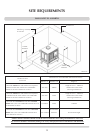
Rear flue pipe installation
1.6 Typical rear flue installation. Flue to be installed in
accordance with flue manufacturers instructions.
PR7218S
Seal Collar with Fire Cement
Self Tapping Screw
Tee
Size Stovax Part No.
6" 4616
Cap
1.7 Connect a tee by inserting it into the flue spigot and
sealing using fire cement and secure with a suitable self
tapping screw. The cap supplied with the tee is used as
the cleaning access. Do not use a 90° elbow to make this
connection.
Top flue pipe installation
1.8 Typical top flue installation. Flue to be installed in
accordance with flue manufacturers instructions.
PR7219S
Self tappping
screw at rear
Flue Pipe 915mm (3ft)
Size Stovax Part No.
6" 4602
Seal flue collar with
Fire Cement
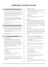
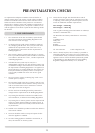
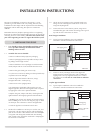
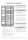
Because each installation is unique to the property, it is not
possible to give full details to suit every setting. However, the
installation should comply with the requirements of the Building
Regulations and be made using "best practice" construction
methods.
Remember that many fireplace openings will have a supporting
lintel. Do not remove this without making provision to support the
remaining structure of the building. The stove must not form any
part of the supporting structure or support the full flue system.
1. INSTALLING THE STOVE
1.1 Care should be taken when handling and fitting stoves
as it is possible to damage the finish with careless
handling and use of tools.
1.2 Assemble the stove as detailed:
• Remove cardboard and polystyrene packaging
• Remove packaging between top baffle and top of stove
by pulling it out through rear flue
• Remove both doors and 4 packages (6 with thermostat
model, ashpan and set of nuts and bolts from the stove
• Remove the grate (fixed grate version only)
• Lay the stove on its back, making sure the top baffle stays
in position and is not damaged
• Bolt the legs to the bottom of the stove, using 1
hexagonal bolt and 1 washer per leg
• Return stove to the upright position
• Fit thermostat (if applicable), following the rear view
diagram opposite, after first removing the knock out panel
by tapping the centre with a pointed hammer
• Replace the grate, ashpan and doors, checking that the
right-hand door closes tightly against the left-hand door
• (Riddling grate version only) Slacken off central retaining
bolt on riddling lever (see rear view diagram, page 4). Slide
on telescopic lever extension as shown. Re-tighten bolt
• Hook ash lip plate on to bottom front of stove
1.3 Decide if the installation is to be top or rear flue exit, and
fit and seal, with fire cement, the flue collar and blanking
plate to suit. The flue collar attaches to the stove backplate
or top plate with hexagonal headed bolts. The blanking
plate is fixed to the unused flue outlet with a clamping bar
secured with a central bolt.
INSTALLATION INSTRUCTIONS