


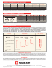
COMBUSTION AIR AND VENTILATION
Combustion air and venting requirements for all gas-fired heating equipment must be provided per the National Fuel Gas Code NFPA54 or the authority having jurisdiction over the
installation. In contaminated atmospheres or high humidity areas, optional outside air for combustion can be supplied. Heaters can be common vented, vented, or indirect vented.
Refer to the Installation and Operation Instructions for further information. A vented installation must be vented to the outside of the building with a flue pipe. An Indirect vented in-
stallation requires a minimum ventilation flow of 4 CFM per 1000 Btu/hr of total installed heater capacity on natural gas by either gravity or power ventilation (4.18 CFM per 1000 Btu/hr
for propane). For indirect vented applications, building exhaust openings must be located above the level of the heaters and inlet air openings must be located below the level of the
heaters.
FOR YOUR SAFETY
OPERATE SPACE-RAY GAS INFRARED HEATERS WITH PROPER CARE AND OBSERVE ALL SAFETY PRECAUTIONS. Installation and service must be performed by a licensed con-
tractor. The installation must conform to local codes. In the absence of local codes, the installation must conform to the National Fuel Gas Code ANSI Z223.1 (latest edition, also known
as NPFA54) or CAN / CSA-B149 installation codes (latest edition). These codes are available from the National Fire Protection Association, Inc., Batterymarch Park, Quincy, MA 02269
or the Canadian Gas Association, 55 Scarsdale Road, Toronto, Ontario MB3 2R3 Canada.
A Division of Gas-Fired Products, Inc.
P.O. Box 36485 Charlotte, NC 28236 Telephone (Toll Free) 1-800-438-4936 (704) 372-3485 Fax (704) 332-5843
Copyright 2008, GFP INC. 050810M FORM#S45600
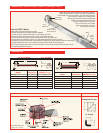
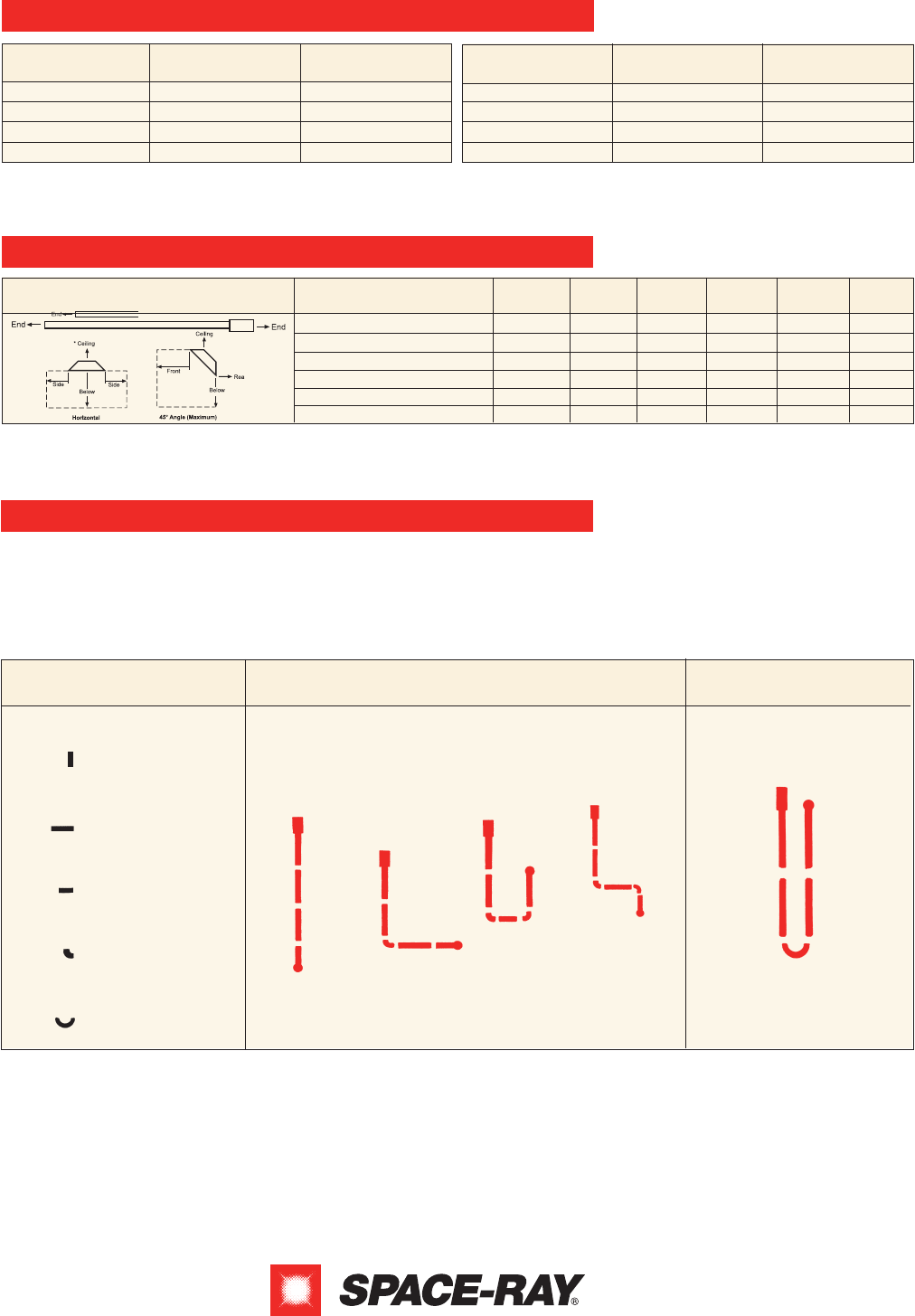
ETS/ETU SERIES LAYOUTS
The PTS/PTU series, with more than 100 different configurations, offers optimum flexibility in custom designing an infrared
heating system. The PTS series is available in multiple configurations (straight, L, Z, and expanded U-shape) with lengths
from 10’ to 70’ long. For added versatility, 90° elbows, corner reflectors, and side reflectors are available for close area
mounting near walls, doors, and corners. The PTU series is available in seven different configurations and provides more
uniform radiant heat energy distribution. The PTU series is ideal for high heat loss areas and spot heating.
PTS/PTU SERIES LAYOUTS
www.spaceray.com • email: info@spaceray.com
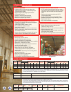
MINIMUM RECOMMENDED MOUNTING HEIGHTS
MINIMUM CLEARANCES TO COMBUSTIBLES
MODEL
MODEL
PTS/U 40
PTS/U 50
PTS/U 75
PTS/U 100
10 feet
11 feet
13 feet
14 feet
9 feet
10 feet
12 feet
13 feet
PTS/U 125
PTS/U 150
PTS/U 175
PTS/U 200
14 feet
15 feet
16 feet
18 feet
13 feet
14 feet
15 feet
17 feet
HEIGHT AT
HORIZONTAL
HEIGHT AT
45° ANGLE
PTS/U (40, 50)
PTS/U (75)
PTS/U (100)
PTS/U (125)
PTS/U (150, 175)
PTS/U (200)
M
INIMUM CLEARANCES TO COMBUSTIBLES
MODEL NO.
SIDE
CEILING BELOW END
(45°)
FRONT
(45°)
REAR
27”
27”
66”
66”
84”
86”
6”
6”
6”
6”
6”
18”
40”
60”
88”**
101”**
106”**
132”**
30”
30”
40”
40”
48”
48”
48”
48”
66”
66”
84”
84”
12”
12”
20”
20”
24”
24”
*When used indirect vented, clearances to ceiling from top of exhaust hood must be 12” on PTS/U (50-75), and 18” on PTS/U (100-200). If optional corner or U-bend reflec-
tors are not used, clearance must be 18”. **Clearance below the tube reduces to 72” 20 ft. downstream from the control box. Note: Consult factory if reduced clearances
are required.
This chart is intended as a guide only, as heaters may be mounted at various heights and angles. Since straight tube heaters are always hotter at the burner end
t
han at the exhaust end, always observe the minimum recommended mounting heights shown above and mount heaters as high as possible. Use PTU series for
s
pot heating. Please consult your local Space-Ray Representative for a detailed analysis of your particular infrared heating requirements.
HEIGHT AT
HORIZONTAL
HEIGHT AT
45° ANGLE
LEGEND
Burner Box
10 FT. BODY SECTION
5 FT. BODY SECTION
90° ELBOW
180° U BEND
PTS SERIES PTU SERIES
40 FT SYSTEM
STRAIGHT
L-SHAPE
EXPANDED
U-SHAPE
Z-SHAPE
40 FT SYSTEM