


9
G
Please read these operating
instructions carefully.Follow the
information given.Use the oper-
ating instructions to get acquaint-
ed with the proper use of your
Petrol-driven Motor Pump.
A
For safety reasons, peo-
ple who are not familiar
with these operating instruc-
tions should not use this
Petrol-driven Motor Pump.
Keep these operating instruc-
tions in a safe place.
Following the operating instruc-
tions supplied by the manufac-
turer is a prerequisite for the
proper use of the pump.
GARDENA Petrol-driven Motor Pump 7000/3 2 T
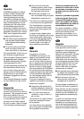
1. Information concerning the Operating Instructions
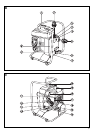
1
Carrying frame
2
Outlet, delivery side
(female thread G1)
3
Inlet, suction side
(female thread G1)
with backflow preventer
4
2 universal pump adaptors
33.3 mm (G 1)
5
Feed opening with seal
6
Outlet with seal
7
Seal
8
Hydraulics housing lid
9
8 Allen screws
0
Fuel filler cap
A
Petrol cock
B
Petrol hose
C
Carburettor
D
Throttle lever
E
Choke lever
F
Starter handle
G
Stop button
(EMERGENCY STOP)
H
Spark plug connector
I
Clamp for air filter
J
Air filter lid
3. Functional Parts (ill. B/C)
GARDENA Petrol-driven Motor
Pumps have been designed for
private use around your house
and garden.
Petrol-driven Motor Pumps are
predominantly used for operating
watering equipment and systems
in private gardens.
Besides, the GARDENA Petrol-
driven Motor Pump can be used
for draining swimming pools,
distribution of water-soluble fer-
tilisers and pesticides as well
as for pumping lime paints and
water-soluble wood preservatives.
A
The GARDENA Petrol-
driven Motor Pump is
not designed for continuous
operation (e.g. industrial appli-
cation, continuous circulating
operation).
A
Corrosive, easily com-
bustible, aggressive or
explosive substances (e.g.
petrol, petroleum or nitro thin-
ner, salt water as well as food)
must not be pumped.
The temperature of the liquid
must not exceed 40°C.
2. Proper Use
4.1 Positioning and Filling
the Pump
A
.Locate pump at safe
distance from the liquid.
.Fill the pump with at least
0.8 l of the liquid to be
pumped via the feed opening
5
or the delivery side
2
every time before you turn
on the pump.
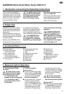
4.2 Hose Connection
Suction side
3
.Screw one of the pump adap-
tors provided
4
true-to-side
(ill. B) into the inlet side of the
pump and screw tight until
the seal is pressed in.
.At the suction inlet, a vacuum-
resistant suction hose has
to be screwed tight onto the
pump, e.g. GARDENA Suction
Hose, art.no. 1412.The built-
in backflow preventer at the
suction inlet
3
prevents dry-
running of the suction hose
when the operation is stopped.
In addition it provides reduced
suction time when starting
the pump again.
A
.For the suction inlet
don’t use any fittings of
the hose connection system!
Delivery side
2
.Screw the second pump adap-
tor true-to-side into the deliv-
ery side
2
of the pump and
screw tight. Ensure that the
4. Measures before Operation