


APPENDIX
A
P-13
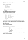
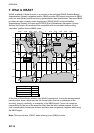
6. Principle of Satellite Compass
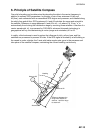
Own ship's heading can be determined by decoding the data in the carrier frequency in
addition to ordinary GPS parameters. In principle, a pair of two antennas A1(ref) and
A2(fore), each connected with an associated GPS engine and processor, are installed along
the ship's fore-and-aft line. GPS systems at A1 and A2 calculate the range and azimuth to
the satellite. Difference in range between A1 and A2 is ∆λ + nλ where λ is 19 cm. “n” is
automatically found during the initialization stage by receiving three satellites. A fraction of a
carrier wavelength, ∆λ, is processed by FURUNO’s advanced kinematic technology in
geographical survey, thus determining a vector (range and orientation) A1 to A2.
In reality, a third antenna is used to reduce the influence of pitch, roll and yaw, and five
satellites are processed to process 3D data. If the GPS signal is blocked by a tall building or
the vessel is under a bridge, the 3-axis solid-state angular rate gyros in the processor unit
take place of the satellite compass, maintaining the current heading continuously.
Heading
θ
Antenna A1
Antenna A2
Antenna A3
Difference between the
range from satellite to
antenna 1 and the range
to antenna 2.
nλ
∆λ
λ
Fore-and-aft line
Vector to decide heading