


En-4
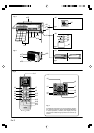
NAME OF PARTS
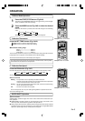
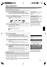
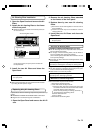
Fig. 6 Remote Control Unit
b1 Signal Transmitter
b2 MODE button
b3 MIN.HEAT button
b4 COIL DRY button
b5 SLEEP button
b6 TIMER MODE button
b7 FAN button
b8 START/STOP button
b9 SET button (Vertical)
b10 SET button (Horizontal)
b11 SWING button
b12 SET TEMP. button (
/ )
b13 TIMER SET (
/ ) button
b14 CLOCK ADJUST button
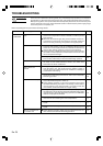
b15 TEST RUN button
● This button is used when installing the air
conditioner, and should not be used un-
der normal conditions, as it will cause the
indoor unit’s thermostat function to oper-
ate incorrectly.
● If this button is pressed during normal op-
eration, the indoor unit will switch to test
operation mode, and the Indoor Unit’s OP-
ERATION Indicator Lamp and TIMER Indi-
cator Lamp will begin to flash simultane-
ously.
● To stop the test operation mode, press the
START/STOP button to stop the air
condi-
tioner.
b16 RESET button
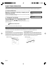
c1 Remote Control Unit Display (Fig. 7)
c2 Temperature SET Display
c3 Operation Mode Display
c4 COIL DRY Display
c5 SLEEP Display
c6 Transmit Indicator
c7 Fan Speed Display
c8 SWING Display
c9 Timer Mode Display
c10 Clock Display
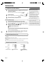
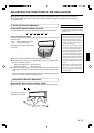
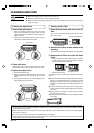
Fig. 1 Indoor Unit
a1 Operating Control Panel (Fig. 2)
a2 MANUAL AUTO button
●
When kept on pressing the MANUAL
AUTO button for more than 10 seconds,
the forced cooling operation will start.
● The forced cooling operation is used at the
time of installation.
Only for authorized service personnel's
use.
● When the forced cooling operation starts
by any chance, press the START/STOP but-
ton to stop the operation.
a3 Indicator (Fig. 3)
a4 OPERATION Indicator Lamp (green)
a5 TIMER Indicator Lamp (orange)
●
If the TIMER indicator lamp flashes when
the timer is operating, it indicates that a
fault has occurred with the timer setting
(See Page 16 Auto Restart).
a6 DEFROST Indicator Lamp(yellow)
a7 COIL DRY Indicator Lamp (yellow)
a8 Remote Control Signal Receiver
a9 Open Panel (Fig. 4)
a10 Front Panel
a11 Air Filter
a12 Airflow Direction Louver
a13 Right-Left Louver
(behind Airflow Direction Louver)
a14 Drain Hose
a15 Air Cleaning Filter
a16 Power Diffuser
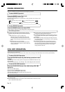
Fig. 5 Outdoor Unit
a17 Intake Port
a18 Outlet Port
a19 Pipe Unit
a20 Drain port (bottom)