


3
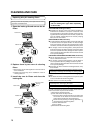
D
E
F
K
M
G
H
I
L
N
J
O
T
U
V
W
X
Q
S
R
P
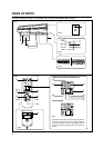
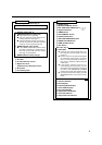
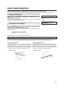
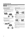
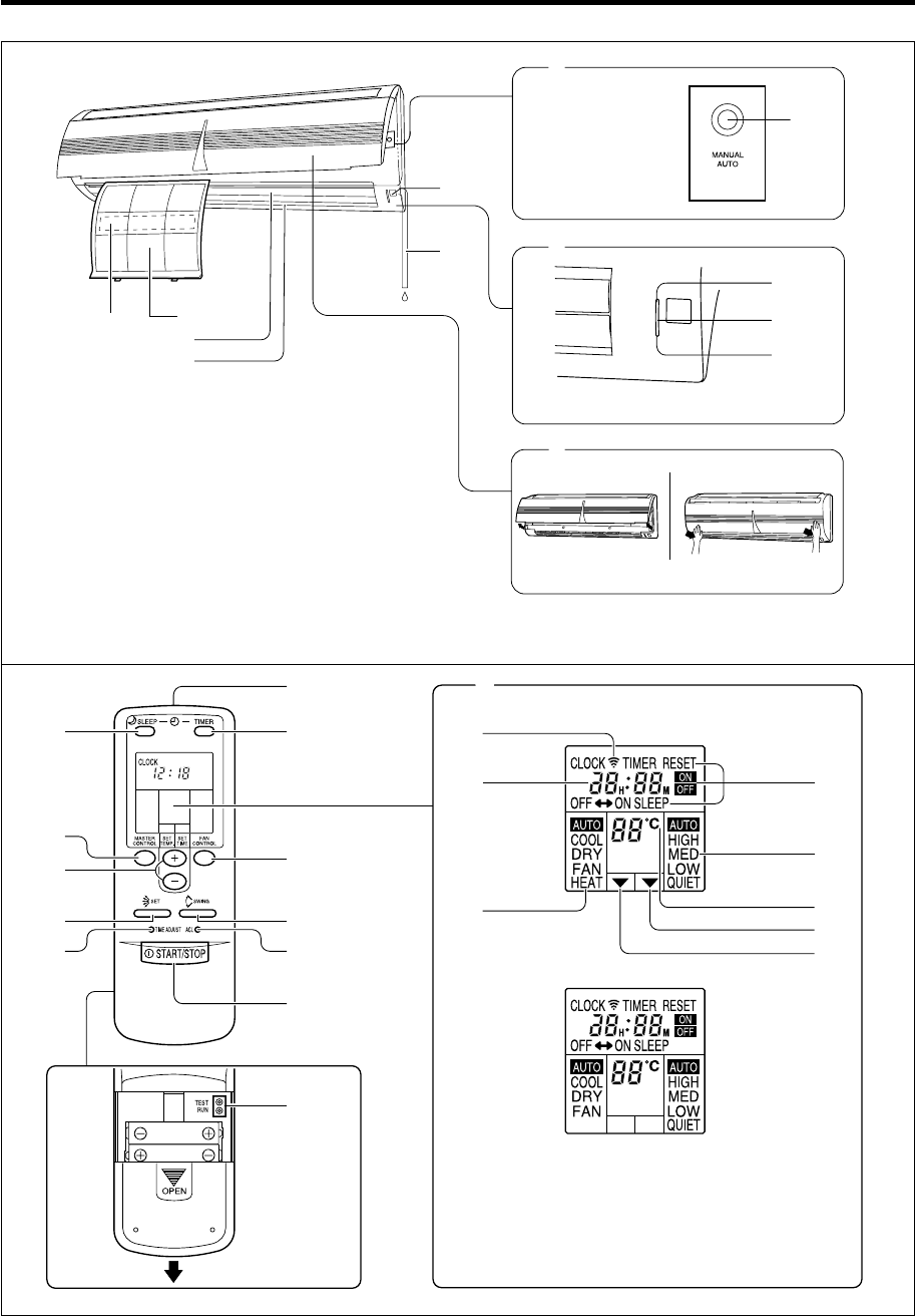
NAME OF PARTS
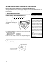
Fig. 5
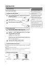
Fig. 1
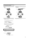
Fig. 2
Fig. 3
Fig. 4
Fig. 7
To facilitate explanation, the accompanying illustra-
tion has been drawn to show all possible indicators;
in actual operation, however, the display will only
show those indicators appropriate to the current op-
eration.
Fig. 6
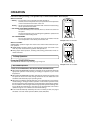
Instructions relating to heating (*) are applicable only to “HEAT & COOL MODEL” (Reverse Cycle).
* HEAT & COOL MODEL (REVERSE CYCLE)
COOLING MODEL
A
0
C
3
1
4
5
6
8
7
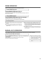
OPERATION
TIMER
SWING
B
9
2