


En-5
NAME OF PARTS
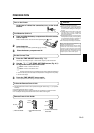
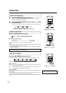
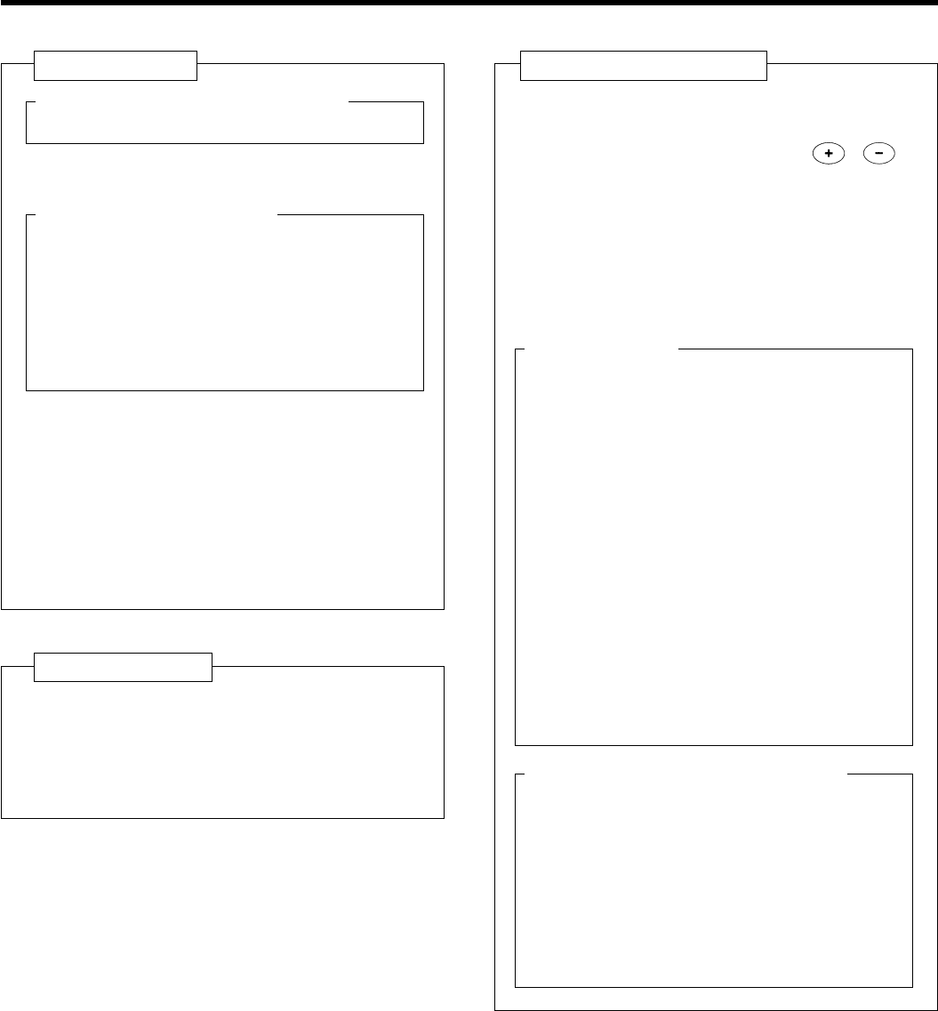
Fig. 6 Remote Control Unit
& SLEEP button
* MASTER CONTROL button
( SET TEMP. /SET TIME button ( / )
) Signal Transmitter
_ TIMER button
+ FAN CONTROL button
¡ START / STOP button
™ AIR FLOW DIRECTION button
£ SWING LOUVER button
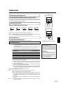
Rear side (Fig. 7)
¢ TIME ADJUST button
∞ ACL button
(located inside battery compartment)
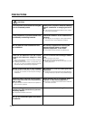
§ TEST RUN button
÷ This button is used when installing the unit,
and should not be used under normal
conditions, as it will cause the air
conditioner's thermostat function to operate
incorrectly.
÷ If this button is pressed during normal
operation, the unit will switch to test
operation mode, and the Indoor Unit's
OPERATION Indicator Lamp and TIMER
Indicator Lamp will begin to flash
simultaneously.
÷ To stop the test operation mode, press the
START/STOP button to stop the air
conditioner.
¶ Remote Control Unit Display (Fig. 8)
• Transmit Indicator
ª Clock Display
º Operating Mode Display
– Timer Mode Display
≠ Fan Speed Display
Ÿ Temperature Set Display
⁄ Timer Set Indicator
¤ Temperature Set Indicator
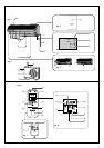
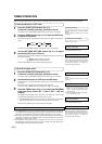
Fig. 1 Indoor Unit
1 Operating Control Panel (Fig. 2)
2 MANUAL AUTO button
3 Remote Control Signal Receiver
4 Indicator Lamps (Fig. 3)
5 OPERATION Indicator Lamp (red)
6 TIMER Indicator Lamp (green)
÷ If the TIMER Indicator Lamp flashes when
the timer is operating, it indicates that a fault
has occurred with the timer setting (See
Page 17 Auto Restart).
7 SWING Indicator Lamp (orange)
8 Intake Grille (Fig. 4)
9 Air Filter
0 Air Flow Direction Louver
- Right-Left Louvers
(behind Air Flow Direction Louver)
= Drain Hose
~ Inter Unit-Line
! Air Cleaning Filter (optional)
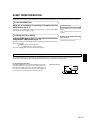
Fig. 5 Outdoor Unit
@ Power Supply
# Intake Port
$ Outlet Port
% Pipe Unit
^ Drain port (bottom)