


En-4
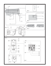
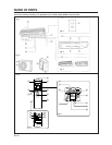
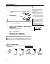
Fig. 1 Indoor Unit
1 Operating Control Panel (Fig. 2)
2 MANUAL AUTO button
3 Remote Control Signal Receiver
4 Indicator Lamps (Fig. 3)
5 OPERATION Indicator Lamp (red)
6 TIMER Indicator Lamp (green)
● If the TIMER indicator lamp flashes when
the timer is operating, it indicates that a
fault has occurred with the timer setting
(see page 17 Auto Restart).
7 SWING Indicator Lamp (orange)
8 Intake Grille (Fig. 4)
9 Air Filter
0 Air Flow Direction Louver
A Right-Left Louvers
(behind Air Flow Direction Louver)
B Drain Hose
C Inter Unit-Line
D Air Cleaning Filter (optional)
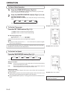
Fig. 5 Outdoor Unit
E Power Supply
F Intake Port
G Outlet Port
H Pipe Unit
I Drain port (bottom)
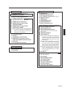
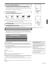
Fig. 6 Remote Control Unit
J SLEEP button
K MASTER CONTROL button
L SET TEMP./SET TIME button (
)
M Signal Transmitter
N TIMER button
O FAN CONTROL button
P START/STOP button
Q AIR FLOW DIRECTION button
R SWING LOUVER button
Rear side (Fig. 7)
S TIME ADJUST button
T ACL button
(located inside battery compartment)
U TEST RUN button
● This button is used when installing the
unit, and should not be used under nor-
mal conditions, as it will cause the air con-
ditioner’s thermostat function to operate
incorrectly.
● If this button is pressed during normal op-
eration, the unit will switch to test opera-
tion mode, and the Indoor Unit’s OPERA-
TION Indicator Lamp and TIMER Indicator
Lamp will begin to flash simultaneously.
● To stop the test operation mode, press the
START/STOP button to stop the air condi-
tioner.
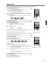
V Remote Control Unit Display (Fig. 8)
W Transmit Indicator
X Clock Display
Y Operating Mode Display
Z Timer Mode Display
[ Fan Speed Display
\ Temperature Set Display
] Timer Set Indicator
` Temperature Set Indicator
NAME OF PARTS