


11
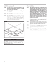
STEP 1 Check the sleeve to be certain it has been correctly installed
in the wall. Remove the front panel on the WSD SLEEVE.
A. Check the anchor screws. There should be four
(4) in the WSD SLEEVE (two in each side).
B. Determine if the sleeve has a downward slope,
to the outside, of ½ bubble on a level. See
page 10 for further details.
C. Check to be sure the sleeve has been sealed
around all edges with an industrial type
ot edis ni dna e
distuo eht htob no gni kluac
prevent rain entry.
D. A sleeve sealing gasket has been provided
in the chassis shipping carton. Remove it
from the carton, peel the protective coating
from the adhesive, and install it in the sleeve
(adhesive down).
STEP 2
Check the electrical receptacle to see that it conforms to
.dellats ni eb ot ledom sissahc eht rof stnemeriuqer eht
See page 3, for the re
.stnemeriuqer elc at pec
Cut/Sever
CAUTION
Although great care has been taken to
minimize sharp edges in the construction
of your unit, use gloves or other hand
protection when handling unit.
Failure to do so can result in minor to
moderate personal injury.
Excessive Weight Hazard
Use two or more people when installing
your air conditioner.
Failure to so can resut in back or other
injury.
CAUTION
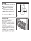
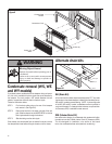
Remove the rear WEATHER PANEL. Reverse grille.
Place lower edge into sleeve tab (Friedrich logo facing out).
Aligns slots with screw holes. Secure grille with screws.
STEP 3
The decorative front is packaged in a separate box inside
dna sissahc eht neewt eb ,notrac gnippihs sissahc eht
the carton. Remove this box and set the box aside until
later.
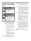
STEP 4 With the help of an assistant, remove the chassis from
the shipping carton. Be careful not to allow anything to
ega mad ni tluser yam siht sa snipriah eht tsniaga tcapmi
to them. With the help of an assistant, lift the chassis by
the basepan and slide it into the sleeve until it contacts
the rear grille. With the chassis in proper position, the
front edge of the basepan must extend out 4 ¾ inches
from the front (side) edge of sleeve.
STEP 5 CHASSIS SEAL GASKET INSTALLATION: After
installing the shell, slide the chassis into the shell stopping
approximately 3" from full insertion. Stuff the chassis seal
gasket one inch deep between the chassis and the she
ll
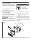
STEP 6 Remove the intake grille from the decorative front frame by
grasping it at the upper right and left side corners. Pull out
.spans gniniater reppu eht morf desaeler si ellirg eht litnu
Tilt it down toward you, lift up and out of the bottom retaining
snaps. Install the decorative front frame in place over the
sleeve opening and attach it to the chassis with four sheet
If foam chassis seal gasket is not installed, the operation
of
the unit will be negatively affected. Also, the operation
noise and outside noise will be amplified.
NOTE: Attach the frame to the chassis by installing four (4)
8A-5/8" screws through the slots in the frame and into the holes in
the chassis.
(see Figure 9, Page 12). Make sure the gasket is installed
beginning from the lower right side corner and extend-
ing over the top and down to the lower left side corner.
Then push the chassis all the way into the shell for the
remaining distance so that the plastic front meets the
front edge of th
e shell.
metal screws as shown in Figure 9, Page 12. Replace
the intake grille by positioning the bottom of the grille
into the bottom retaining snaps. Tilt the front up and
away from you. Press in lightly on top, and the grille will
position retaining snaps. itself into upper
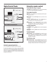
WallMaster chassis installation
instructions for WS, WE and WY
models