


—8—
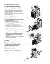
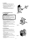
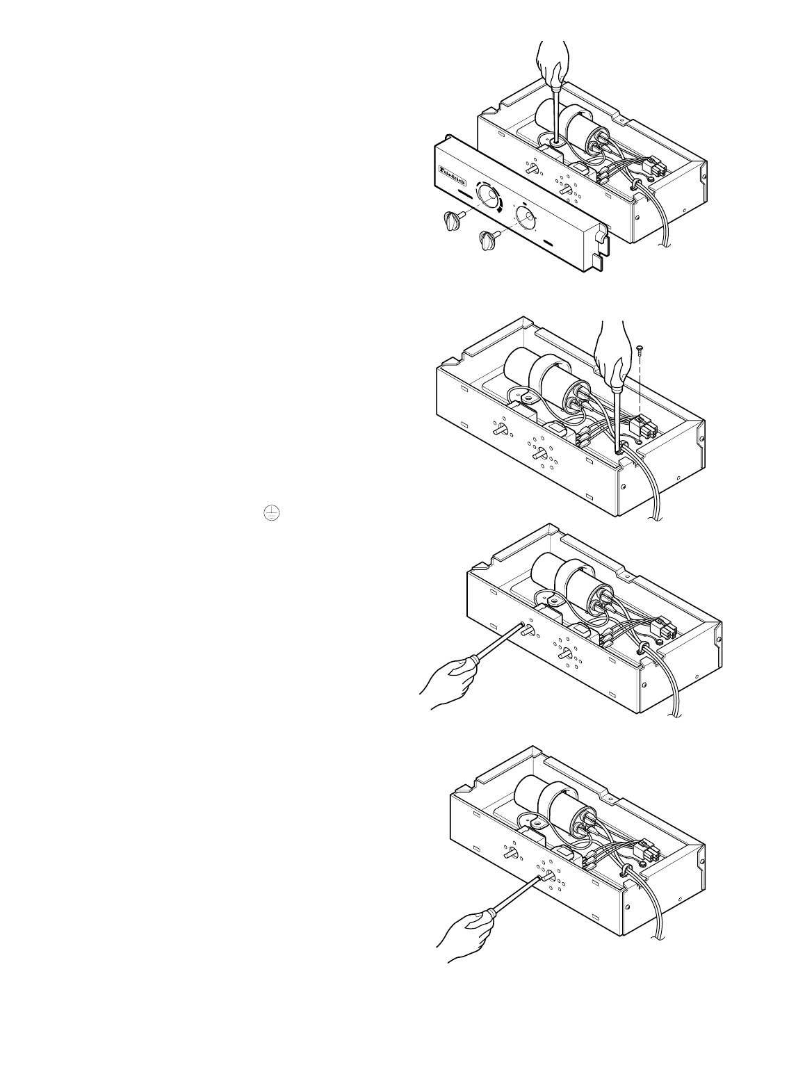
2.3.3 CAPACITOR
1. Remove the cabinet. (Refer to section 2.1.2)
2. Remove the screw and the clamp which fastens the
capacitor.
3. Disconnect all the leads of capacitor terminals.
4. Re-install the components by referring to the
removal procedure, above. (See Figure 11)
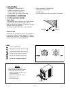
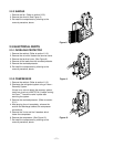
2.3.4 POWER CORD
1. Remove the cabinet. (Refer to section 2.1.2)
2. Disconnect the grounding screw from the control
box.
3. Disconnect the 2 receptacles.
4. Remove a screw which fastens the clip cord.
(See Figure 12)
5. Remove the power cord.
6. Re-install the component by referring to the above
removal procedure, above.
(Use only one ground-marked hole for ground
connection.)
7. If the supply cord of this appliance is damaged, it
must be replaced by the special cord. (The
special cord means the cord which has the same
specification marked on the supply cord attached at
the unit.)
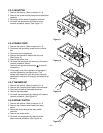
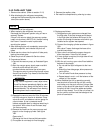
2.3.5 THERMOSTAT
1. Remove the cabinet. (Refer to section 2.1.2)
2. Remove the 2 screws which fasten the thermostat.
3. Disconnect 2 leads of thermostat terminals.
4. Remove the thermostat.
5. Re-install the components by refering to the above
removal procedure. (See Figure 13)
2.3.6 ROTARY SWITCH
1. Remove the cabinet. (Refer to section 2.1.2)
2. Remove the 2 screws which fasten the rotary
switch.
3. Disconnect all the leads of the rotary switch
terminals.
4. Remove the rotary switch.
5. Re-install the components by referring to the
above removal procedure. (See Figure 14)
High
Cool
Med
Fan
Off
M
o
d
e
Med
Cool
Low Cool
Low
Fan
Cooler
Warmer
T
e
m
p
e
r
a
t
u
r
e
Figure 11
Figure 12
Figure 13
Figure 14