


—12—
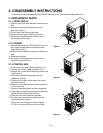
3. INSTALLATION
3.1 HOW TO INSTALL THE UNIT
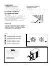
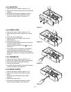
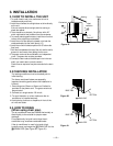
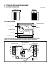
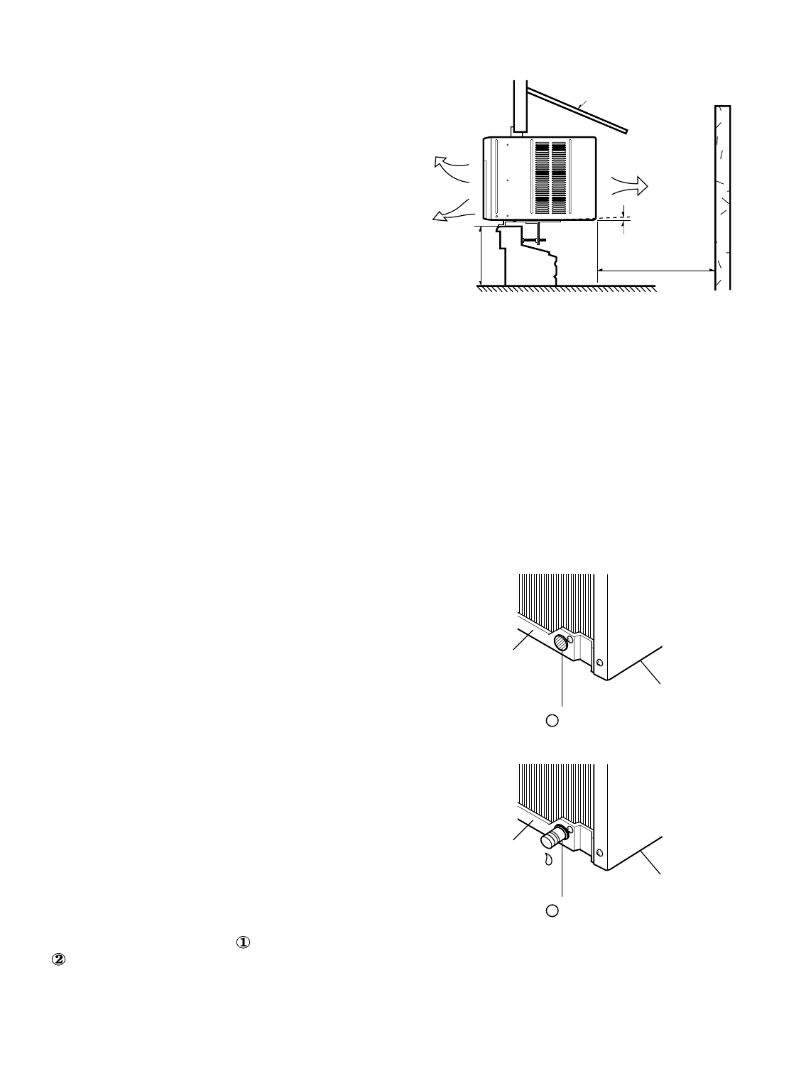
1. To avoid vibration and noise, make sure the unit is
installed securely and firmly.
2. Install the unit where the sunlight does not shine directly
on the unit.
If the unit receives direct sunlight, build an awning to
shade the cabinet.
3. There should be no obstacle, like a fence, within 20"
which might restrict heat radiation from the condenser.
4. To prevent reducing performance, install the unit so that
louvers of the cabinet are not blocked.
5. Install the unit a little obliquely outward not to leak the
condensed water into the room (about 1/4").
6. Install the unit with its bottom portion 30~60" above the
floor level.
7. Stuff the foam between the top of the unit and the wall to
prevent air and insects from getting into the room.
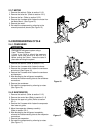
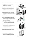
8. The power cord must be connected to an independent
circuit. The green wire must be grounded.
9. Connect the drain tube to the base pan hole in the rear
side if you need to drain (consult a dealer).
Plastic hose or equivalent may be connected to the drain
tube.
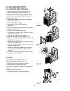
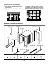
3.2 CHECKING INSTALLATION
The setting conditions must be checked prior to
initial starting.
The items mentioned below are especially
important checking points when the installation is
finished.
1. Grounding wire (Green or Green and Yellow) is
provided in the power cord. The green wire must
be grounded.
2. Connect to a single-outlet 15A circuit.
3. To avoid vibration or noise, make sure the air
conditioner is installed securely.
4 Avoid placing furniture or draperies in front of the
air inlet and outlet.
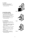
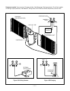
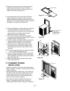
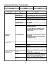
3.3. HOW TO DRAIN
(When using drain pipe)
The air conditioner must be installed horizontally or
tilted slightly to the outside for proper water
drainage.
On exceptionally hot and humid days the air
conditioner may overflow condensed water.
If the air conditioner is used in hot and a high
humidity zone, exchange the DRAIN CAP for the
DRAIN PIPE.(See Figure 20, Figure 21)
About
1
/4"
30"~60"
Awning
Cooled air
Fence
Over 20"
Heat
radiation
BOTTOM
DRAIN CAP
1
BASE PAN
BOTTOM
DRAIN PIPE
2
BASE PAN
Figure 20
Figure 21
Figure 19