


8
920-024-05 (12-04)
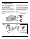
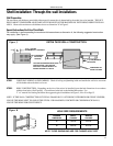
STEP 1 Remove the junction box, cover and screw (above items) from the shipping position underneath the fan motor. Install one
junction box mounting leg in the upper left position facing the rear of the junction box.
STEP 2 Remove and discard the plastic bushing from the conduit connector on the side panel of the control compartment. Strip the
black wires only, approximately 1/2 inch (13 mm).
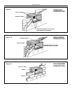
STEP 3 Insert all wires (2 black, 1 green) into the box and thread the box onto the conduit connector until tight. Back off counter
clockwise until the junction box is vertical with the mounting leg at the upper–right position facing the box opening. Be
sure that the shell can fi t between this box and the chassis.
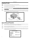
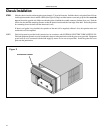
Unpacking The Unit
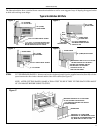
STEP 1 Remove decorative plastic return air grille to a safe area away from the unit.
STEP 2 Remove the installation hardware, wingboard and two (one light colored and one dark colored) gaskets from beneath the
unit, and place them in a safe area away from the unit.
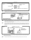
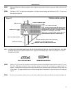
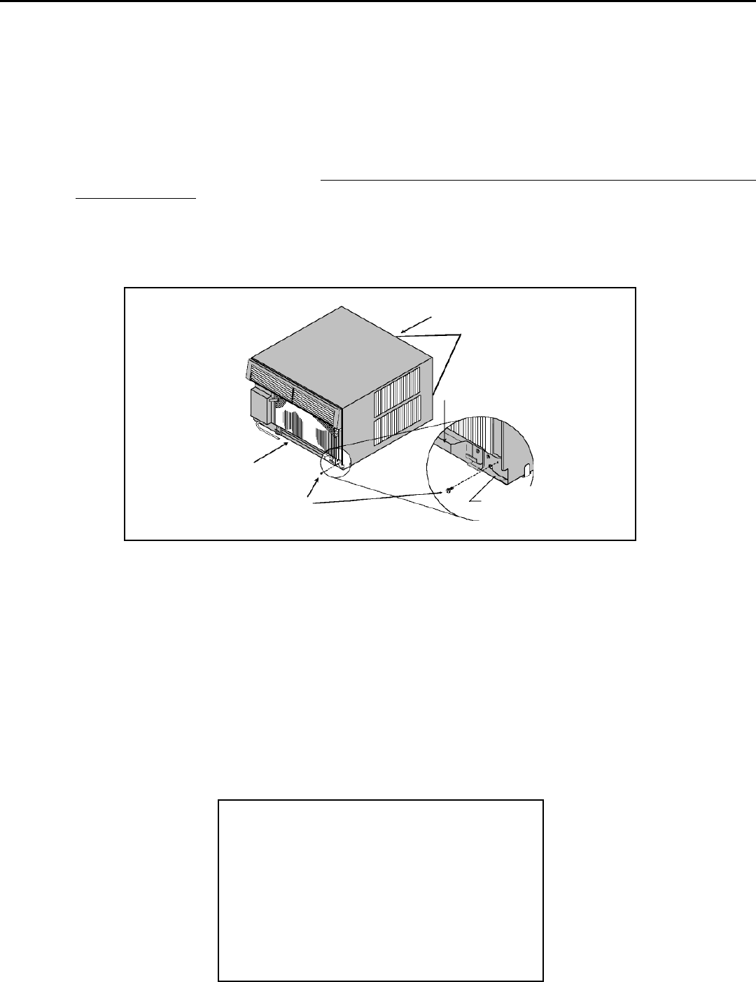
STEP 3 Remove the chassis retainer by removing the far right screw in the basepan (see Figure A); save this screw to reattach the
chassis retainer after installation (Step 15). Also, remove and discard the two retainer screws and plastic bushings located
at the rear of the unit.
STEP 4 While an assistant holds the cabinet stationary, use the hand pull at the front of the base pan (see Figure A) to pull the
chassis out of the cabinet. Remove white foam blocks used to restrain the compressor during shipment. Inspect basepan
for dislodged white blocks, and remove. Do not remove any other foam.
Chassis Wiring and Preparation
CABINET
HAND PULL
CHASSIS RETAINER
FAR RIGHT SCREW
HAND PULL
Figure A
CABINET
STEP 3
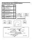
PROVIDED HARDWARE
1 JUNCTION BOX FRIEDRICH PN: 613-893-00
2 MOUNTING LEGS RACO INC. PN: 5324-0
2 LEG SCREWS
2 HOLE COVERS
1 GROUND SCREW
BOX COVER FRIEDRICH PN: 613-892-00
GASKET RACO INC. PN: 5173-0
2 SCREWS
1 SHEET METAL SCREW