


17
www.retroaire.com
The Right Fit For Comfort
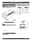
RC/RH80 INSTALLATION INSTRUCTIONS (Continued)
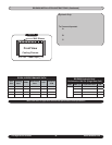
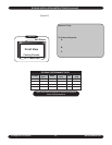
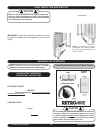
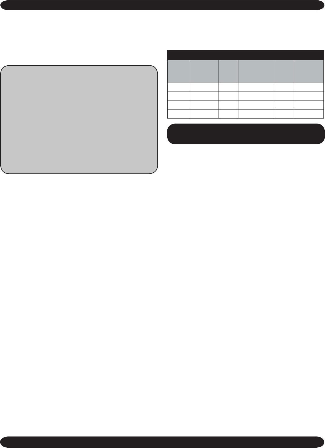
RC/RH80 Performance Date*
UNIT
SIZE
COOLING
BTUH
EER
HEAT PUMP
BTUH
COP
FRESH
AIR CFM
9 9,500 10 8500 2.8 40/35
12 11,900 10 11400 2.9 40/35
15 14,700 9.2 13800 2.8 40/35
18 16,900 9.1 N/A N/A 40/35
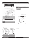
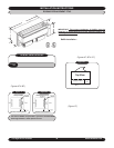
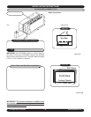
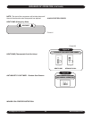
6. Once confident that all seals are the correct size and in
the proper location and the correct baffles are attached
to the condenser coil and in the proper orientation, slide
unit into final position and tighten any tie down bolts or
screws as necessary.
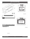
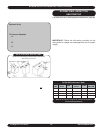
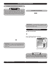
Hydronic Only: Remove the 2-position connector as-
sembly from kit bag supplied with unit (this will have 2
yellow wires attached). Connect this 2-position connec
-
tor to the 2-position connection located on the bottom
of the control box panel.
To Connect Aquastat:
A. Remove the black jumper wire located on the bot-
tom panel of the control box (this is also terminated
with a 2-position connector).
B. Cut the jumper wire in the middle and splice the
Aquastat to the jumper.
C. Place the connecter back into original location.
Refer to wire diagram on the unit for details.
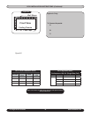
7. Connect line cord.
8. See Final Inspection and Startup on page 20.
*Refer to the charts on page 23 for electrical and optional
electric heat specifications.