


18
www.retroaire.com
The Right Fit For Comfort
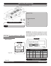
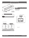
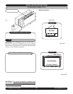
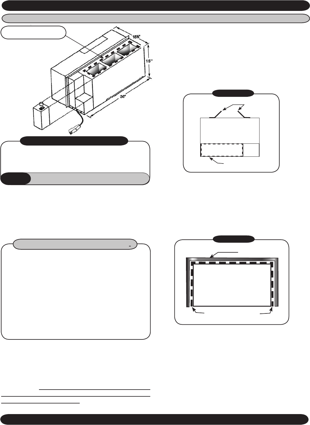
IMPORTANT: The RC/RH90 chassis is 18 1/4” deep for
the 9,000, 12,000, and 15,000
Btuh models. The standard
depth for the 18,000
Btuh is 24”. However, EMI can supply
it for an 18 1/4” chassis on demand.
RC/RH90 REPLACEMENT PTAC
INSTALLATION INSTRUCTIONS
1. Remove unit from box and install duct collar.
• 1 Installation Manual
• 1 Lt. & Rt. Baffl es
• 1 Duct Collar
• 1 Slide-Duct
• Screws
• 1/4” x 3/4” Open Cell Foam Tape
• 1” x 1” Open Cell Foam Tape
• 1/2” x 1/2” Open Cell Foam Tape
HYDRONIC
ONLY
• 1ea. 2-Position Connector & Pin Mate
• 14AWG Yellow Wire
RC/RH90 BAFFLE INSTALLATION KIT
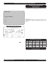
2. Slide unit into wall sleeve. The supply duct on the cool-
ing chassis should line up with the supply vent on the
room cabinet. The weather angles should require no
adjustment.
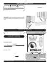
IMPORTANT:
The correct condenser air baffl es must
be installed or performances may be impaired and/or
the warranty will be voided.
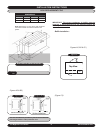
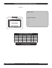
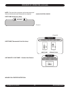
Figure A9
NOTE: CONTROL BOX IS
A SEPARATE PART THAT
IS ELECTRICALLY CON-
NECTED TO THE CHASSIS
ON-SITE.
Install Duct Collar here
3. Baffl e Installation - Remove baffl es from kit bag sup-
plied with unit. Install left and right side baffl es on the
condenser coil in existing holes:
• Baffl es must come in contact with the outdoor louver
• Make sure baffl es are directed inward toward the
center of coil
• Secure baffl es tightly to the condenser coil using the
screws provided (Figure A9)
4. Remove 1/2” x 1/2” open cell foam strips from kit bag
and apply to sheet metal fl anges around the perimeter
of the supply air duct outlet as shown in
Figure A9. Fail-
ure to do so results in recirculation of the conditioned air
around the wall sleeve and through the unit causing the
unit to short cycle, thus raising operating costs through
improper heating and cooling.
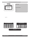
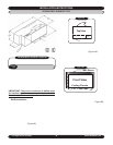
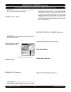
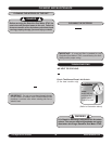
Figure B9
Duct Collar and Slide-Duct Installation
• Remove duct collar and slide-duct from packaging.
• Fasten 1/4” x 1/2” foam tape to the bottom fl anges
of the duct collar, this serves as a gasket between
the collar and the unit.
• Securely fasten duct collar over discharge opening
with screws provided.
• Insert slide-duct into duct collar. (See illustration
above)
5. 1” x 1” Open cell foam strips are provided to prevent
outside air from entering around the chassis to the
room from the sides and top of the cabinet
(Figure B9).
Install between wall sleeve and cooling chassis. It is
imperative to have a solid air seal between wall sleeve
and chassis. Failure to do so will result in air leakage
from outdoor to indoor causing system problems i.e.
coils freezing, short cycling, and constant running of
unit. If installer is in need of more foam than supplied
in kit, consult factory.
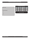
1/2” X 1/2” Supply Air
Duct Foam Tape
Baffl es-Directed Inward
Toward Coil
Front View
Cooling Chassis
Wall Sleeve
1x1 Foam Tape