


12
2) Electrical
A. Grounding
CAUTION: The unit must be electrically wired and grounded in accordance with all state and local codes, national electric
code, and NFPA 70. Unit and controls will NOT operate unless properly grounded. A ground lug is provided for ground
connection. Use only approved copper wire and connectors from unit to service panel.
B. Power Supply
NOTE: Line voltage circuit is completely factory wired. Make all line voltage connections inside circuit breaker junction box.
The circuit breakers or fuses used for branch circuit protection should be UL recognized. If circuit breakers are used, the circuit
breaker for the compressor circuit must have a UL HACR rating. If fuses are used, the fuse for the compressor circuit MUST
be time delay type.
CAUTION: Units are dual voltage rated 208-230/1/60. The 24V control transformer must be connected for either 208V
or 240V power source for proper operation. Line voltage must not exceed 253V or go below 197V. The transformer
connection must be changed for 208V operation.
Depending on auxiliary heater size, unit must be supplied with 2 or 3 separate 208V or 240V circuits from structure’s fuse
box or service panel. Each circuit is internally connected to a circuit breaker located in the unit control box located at the
front center of the unit. Refer to Table 4 and Table 5 for required circuits and recommended wire size for each circuit.
DANGER: Electrical shock hazard. Turn OFF electric power at the fuse box or service panel before making any
electrical connections and ensure a proper ground connection is made before connecting line voltage. Failure to do
so can result in property damage, personal injury and/or death.
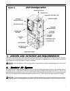
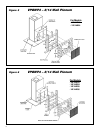
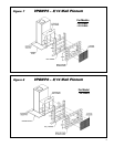
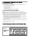
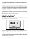
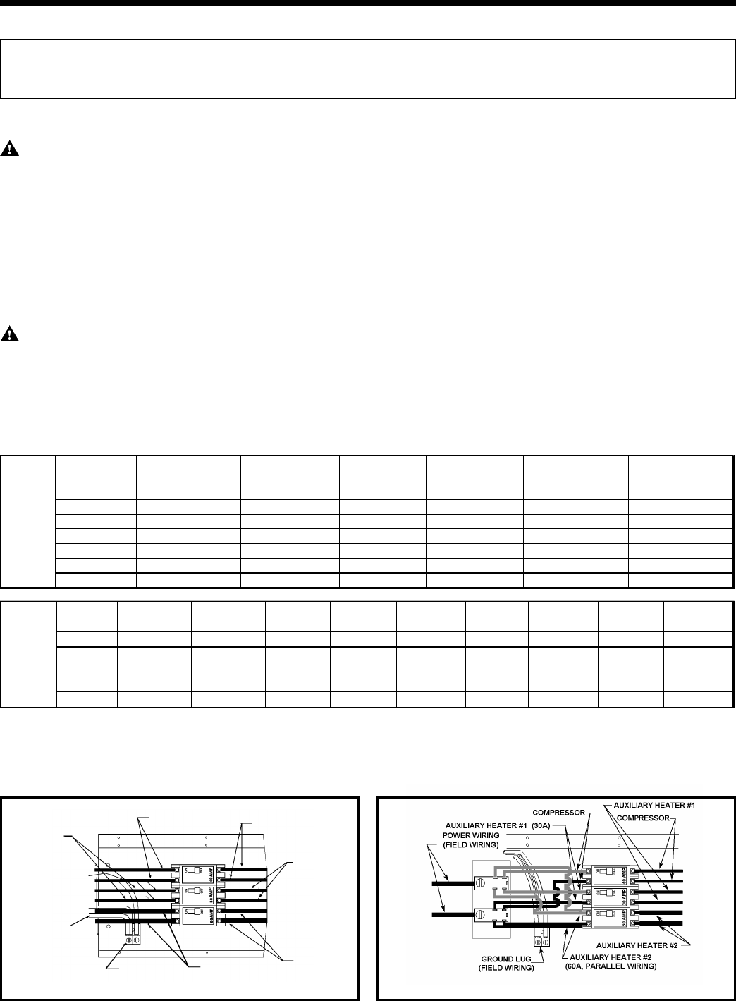
Unit Wiring with VPDB1 Distribution Block
1
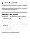
If wire is applied at ambient greater than 30°C (86°F), consult Table 310-16 of the NEC (ANSI/NFPA 70). The ampacity of nonmetalic-sheathed
cable (NM), trade name ROMEX, shall be that of 60°C (140°F) conductors, per the NEC (ANSI/NFPA 70) Article 336-30. If other than uncoated (non-
plated), 60°C or 75°C (140°F or 167°F) insulation, copper wire (solid wire for 10 AWG and smaller, stranded wire for larger than 10 AWG) is used,
consult applicable tables of the NEC (ANSI/NFPA 70).
2
Time-delay fuse.
3
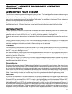
Circuit #3 is only used for 25kw heater.
Heat Pump
(Field Wiring)
Auxiliary
Heater #1
(Field Wiring)
Ground
(Field Wiring)
Ground Lug
Auxiliary Heater #2
(Field Wiring)
Auxiliary
Heater #2
Auxiliary
Heater #1
Heat Pump
Line Voltage And Ground Connections
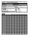
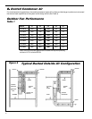
Model Compressor Amps Outdoor Fan Amps Indoor Fan Amps
Minimum Circuit
Ampacity Minimum Wire Size
1
Maximum Fuse
2
or
Breaker Size Amps
V(E,H)B18
9.3 1.4 1.0 14.0 12 20
V(E,H)B24
11.4 1.4 1.0 16.7 12 25
V(E,H)B30
15.0 2.2 1.8 22.8 10 30
V(E,H)B36
17.9 3.0 2.5 27.9 8 40
V(E,H)B42
20.4 4.5 3.0 33.0 8 50
V(E,H)B49
26.4 5.0 3.0 41.0 6 60
V(E,H)B60
32.1 5.0 3.1 49.0 6 60
Cooling and Fan
Circuit Data
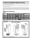
Heater Size
(KW)
Chassis
Available Ckt #1 Amps
Ckt #1
Ampacity
Ckt #1 Wire
Size
1
Ckt #1 Max.
Fuse
2
Ckt #2 & 3
3
Amps
Ckt #2 & 3
3
Ampacity
Ckt #2 & 3
3
Wire Size
1
Ckt #2 & 3
3
Max. Fuse
2
5.0
18/24 20.8
26.0
10
30
N/A N/A N/A N/A
10.0
18/24/30/36/42 41.6
52.0
6
60
N/A N/A N/A N/A
15.0
30/36/42/48 20.8
26.0
10
30
41.6
52.0
6
60
20.0
48/60 41.6
52.0
6
60
41.6
52.0
6
60
25.0
60 20.8
26.0
10
30
41.6
52.0
6
60
Heat Strip Data