


11
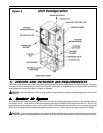
C. Indoor-Air (Conditioned Supply Air) System
The VEB/VHB series unit may be applied in either a free return air configuration or a ducted return air configuration. The supply
air path is intended to be ducted. The design and construction of the indoor-air system must provide adequate air distribution
to ensure comfort levels throughout the structure.
The combined pressure losses of the return and supply air paths must not exceed the external static capabilities of the system
at the design airflow (See Table 2).
If the unit is installed in a closet behind a door and the return air louver or grille is directly opposite the unit RA opening, 2-
in. clearance is required between the front of the unit and the back side of the louver or grille. If the louver or grille is located
elsewhere on the door so it is not directly in front of the RA opening, a minimum of 7-in. clearance is required between the
front of the unit and the back side of the door. The minimum "net free open area" required for the RA louver or grille is listed
in Table 2.
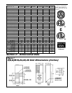
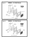
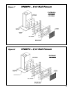
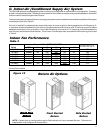
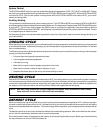
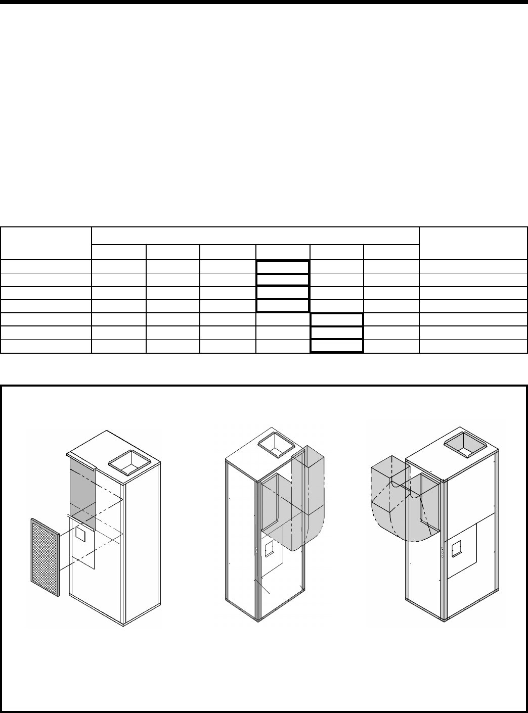
Return Air Options
Front FreeFront Free
Front FreeFront Free
Front Free
ReturnReturn
ReturnReturn
Return
Side Ducted
Return
Front Ducted
Return
Figure 10
NOTE: Ducted return air configurations require field fabrication of a duct-mounted filter box. Filters are not
supplied with units configured for ducted return.
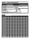
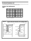
Indoor Fan Performance
Table 2
Indoor Blower Air Flow, SCFM (ARI RATED as shown)
Model ESP 0.1 0.2 0.3 0.4 0.5
VE/HB18 Indoor
850
750 640 550
450
250
VE/HB24 Indoor
980
890 800 720
650
300
VE/HB30 Indoor
1120
1070 1000 940
830
375
VE/HB36 Indoor
1220
1120 1050 990
860
400
VE/HB42 Indoor
1570
1510 1470 1400 1350 525
VE/HB49 Indoor
1670
1610 1570 1500 1450 525
VE/HB60 Indoor
1980
1920 1860 1800 1700 675
Note:
Italic
indicates performance outside the required operating window of +/- 10% of rated SCFM. All values are wet
coil with filter installed.
RA Grille Minimum Net
Free Open Area (Sq. In.)