


www.desatech.com
119360-01B
2
Left Side Leg
Assembly
Right Side Leg
Assembly
Header
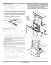
Figure 3 - Installing Header
5. Position header between leg assemblies with direction
arrow pointing up (see Figure 3). Attach header to leg
assemblies through predrilled holes with 1
1
⁄4" screws
in each leg assembly as shown in Figure 4. You may
prefer to lay mantel face down on a soft surface instead
of upright. Using pocket holes and 1
1
/
4
" screws, attach
header to leg assemblies. Be sure you have proper align-
ment between the header and leg assemblies. Attach at
brackets with 1/2" or 3/4" screws using 1 at bracket and
4 screws per side (see Figure 4).
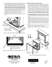
Top of
Mantel
Figure 5 - Placing Mantel Assembly onto Mantel Top
Figure 4 - Attaching Header to Leg Assembly
Top
Leg
Assembly
Header
Left Side Leg
Assembly
Header
1
1
/
4
" Screw
Legs Should Be
Flush With Top
Screws
Small
Gap
Make certain
spacing is the
same front and
back.
Figure 6 - Attaching Top to Leg and Header Assembly
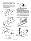
Flat Bracket
1/2" or 3/4" Screws
Brackets
1/2" or 3/4" Screws
Screw
Figure 2 - Attaching Brackets
ATTACHING TOP OF MANTEL
1.
Turn top (#7) and leg assembly upside down on soft surface.
Place header/leg assembly inside top (see Figure 5).
2. Make sure mantel is centered left to right inside top and
rear of legs are ush with back of top. Gap between mantel
top and leg should be the same from front to back (see
Figure 5).
3. Attach side and header assembly to mantel top using 1
1
⁄4" screws inserted through pocket holes (see Figure 6).
4. Attach 3 brackets to assembly using two 1/2" or 3/4" screws
per bracket. One bracket should be in center of header
and the other two toward back of leg assembly on each
side (see Figure 6).
5. With assistance, carefully turn assembly upright.
Bracket with 1/2"
or 3/4" Screw
Figure 1 - Assembling Legs
Leg Side
Leg
Front
1
1
/
4
" Screw for
Pocket Holes
Pocket
Holes
Bottom of
Panel