


www.fmiproducts.com
111026-01J 7
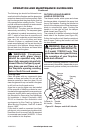
VENTING INSTALLATION
Continued
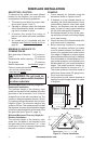
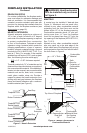
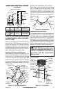
When connecting chimney directly to the replace,
the inner ue pipe section must be installed rst
with the lanced side up. The outer pipe section
can then be installed over the ue pipe section with
the hemmed end up. Press down on each pipe
section until the lances securely engage the hem
on the replace starter. The wire will assure the
proper spacing between the inner and outer pipe
sections. Continue to assemble chimney sections
as outlined, making sure that both the inner and
outer pipe sections are locked together. When
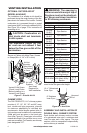
installing double wall snap-lock chimney together,
it is important to assure the joint between the chim-
ney sections is locked. Check by pulling chimney
upward after locking. The chimney will not come
apart if properly locked. It is not necessary to add
screws to keep the chimney together (exception -
see Figure 9, page 8).
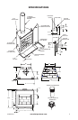
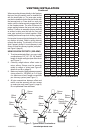
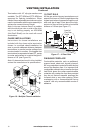
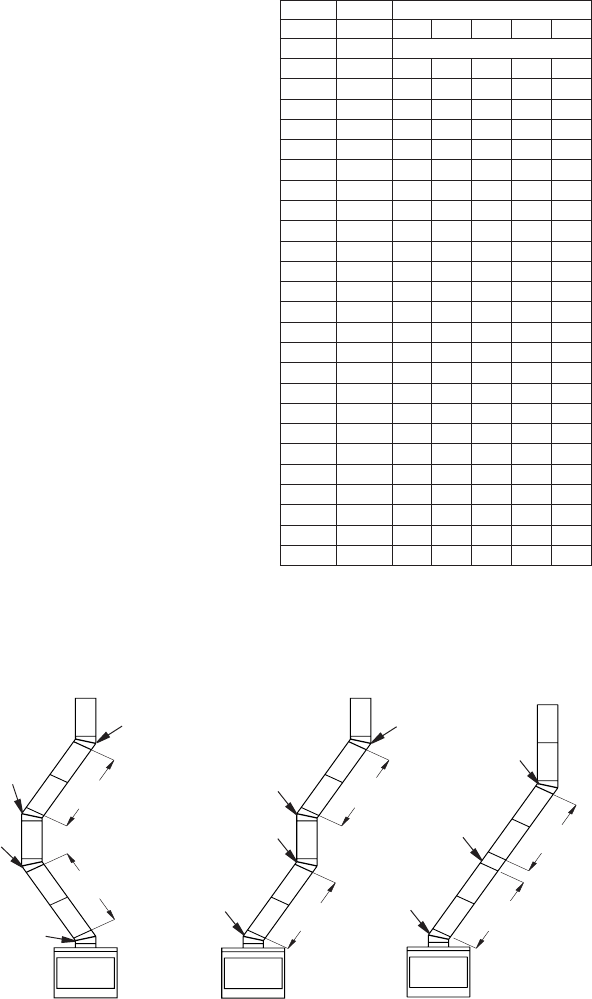
USING ELBOW OFFSETS (30E-8DM)
1. To achieve desired offset, you may install
combinations of 12", 18", 24", 36" and 48"
length of double wall pipe (see offset chart
and Figure 7).
2. Chimney weight above offset rests on
return elbow. Straps must be securely
nailed to rafters or joists (see Figure 8,
details A and B on page 8).
3. Maximum length of pipe between supports
(return elbow or 12S-8DM) is 6' of angle
run. Maximum of two 6' angle run sections
per chimney system (see Figure 7).
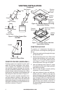
4. All pipe connections between offset and
return must be secured with two screws
on outer pipe only (see Figure 9, page 8).
Do not penetrate inner stainless.
OFFSET
RISE CHIMNEY LENGTH
A B 48" 36" 24" 18" 12"
4
3
/
8
" 16
3
/
8
"
ELBOW SET ONLY
9
3
/
4
" 25
1
/
2
"
1
12
3
/
4
" 30
3
/
4
"
1
15" 34
3
/
4
"
1
18" 40"
1 1
21
1
/
4
" 46
1
/
4
"
1
23
3
/
4
" 49
1
/
4
"
1 1
27
3
/
4
" 56
3
/
4
"
1
30" 60
3
/
4
"
1 1
33" 66"
1 1
36" 71"
1 1
38
1
/
4
" 75"
2
41
1
/
4
" 80
1
/
4
"
1 1 1
45" 86
3
/
4
"
2
46
3
/
4
" 89
1
/
2
"
1 1 1
51" 97"
1 1
53
1
/
4
" 101"
2 1
56
1
/
4
" 106
1
/
4
"
2
59
1
/
4
" 111
1
/
2
"
1 1 1
61
3
/
4
" 115
1
/
2
"
2 1
64
3
/
4
" 120
3
/
4
"
2 1
68
1
/
4
" 127"
1 2
70" 130"
2 1 1
74
1
/
4
" 137
1
/
2
"
1 2 1
76
3
/
4
" 141
1
/
2
"
1 2 1
79
3
/
4
" 146
3
/
4
"
4
OFFSET CHART (22-50 FT. SYSTEM HEIGHT)
Figure 7 - Typical Offset Terminations
Return
Elbow
Offset
Elbow
Return
Elbow
Offset
Elbow
6' Max.
6' Max.
6' Max.
6' Max.
6' Max.
6' Max.
Return
Elbow
Offset
Elbow
Offset
Elbow
Return
Elbow
A B C
Offset
Elbow
Ceiling
Support Pipe
12S-8DM
Return
Elbow