


www.fmiproducts.com
111026-01J6
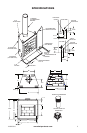
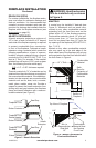
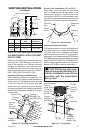
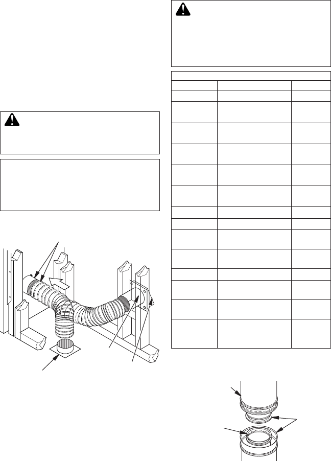
Figure 6 - Lineal Gain
Hemmed
End
8" Stainless
Inner Pipe
12
3
/
8
" Galvanized
Outer Pipe
A
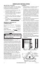
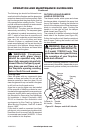
SSEMBLY AND INSTALLATION OF
DOUBLE WALL CHIMNEY SYSTEM
Each double wall chimney section consists
of a galvanized outer pipe, a stainless steel
inner ue pipe and a wire spacer. The pipe
sections must be assembled independently
as the chimney is installed.
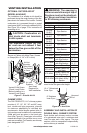
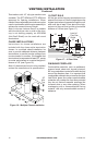
VENTING INSTALLATION
OPTIONAL OUTSIDE AIR KIT
(MODEL AK4/AK4F)
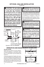
The installation of an outside air kit should be
performed during the rough framing of the re-
place due to the nature of it's location. Outside
combustion air is accessed through a vented
crawl space (AK4F) or through a sidewall (AK4).
See Figure 22 on page 13 for instruction of
operating air kit.
CAUTION: Combustion air
inlet ducts shall not terminate
in attic space.
The maximum height for the
air vent can not exceed 3 feet
below the ue gas outlet of the
termination.
Figure 5 - Outside Air Kit
Secure to Collars with Metal Tape, Screws
or Straps (Min. of 1/4" x 20" in size)
Air Inlet
Location
Must Allow
For Bushes
or Snow
Vent Hood
Required for
Wall Installation
Air Inlet
Eyebrow
Vented Crawl Space
(Check Local Codes
Before Installing in a
Vented Crawl Space)
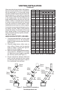
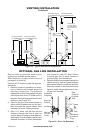
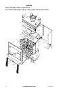
CHIMNEY PIPE
The FMI PRODUCTS, LLC chimney system
consists of 12", 18", 24", 36" and 48" snap-
lock, double-wall pipe segments, planned
for maximum adaptability to individual site
requirements. Actual lengths gained after t-
ting overlaps must be taken into consideration
(lineal gain) and are given in the lineal gain
chart (see Figure 6). Lineal gain is the actual
measurable length of a part after two or more
parts are connected. For Canada, use chimney
parts designated "HT".
WARNING: The opening in
collar around chimney at top of
replace must not be obstruct-
ed. Never use blown insulation
to ll chimney enclosure.
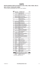
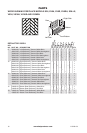
LINEAL GAIN
PART NO. DESCRIPTION GAIN
36" Fireplace 40
"
12-8DM
12-8HT
Pipe Section 10
5
/
8
"
18-8DM
18-8HT
Pipe Section 16
5
/
8
"
24-8DM
24-8HT
Pipe Section 23
5
/
8
"
36-8DM
36-8HT
Pipe Section 34
5
/
8
"
48-8DM
48-8HT
Pipe Section 46
5
/
8
"
RT-8DM Round Termination 6
7
/
8
"
*
RTL-8DM Round Termination 7
3
/
4
"
*
RTT-8DM
Round Termination
with Slip Section
6
7
/
8
" to
23
1
/
8
"*
RTTL-8DM
Round Termination
with Slip Section
8
1
/
2
" to
21
1
/
2
"*
ET-8DM Square Chase-Top 12
"
*
ETO-8DM
Square Chase-Top
with Mesh
12
"
*
ETL-8DM
Square Chase-Top
with Slip Section
7" to 15"*
ETLO-8DM
Square Chase-Top
with Mesh & Slip
Section
12
"
to
25
1
/
2
"
*
* The lineal gain for the terminations is mea-
sured to the ue gas outlet height.