


www.fmiproducts.com
108662-01L16
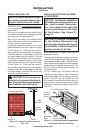
3. Using screws provided, fasten upper
ange of blower bracket to hearth pan and
end anges to leg stands (see Figure 16,
page 15).
Note: The wire assembly must be ar-
ranged in front of and away from fan
blades to reach power receptacle plug.
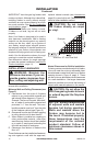
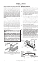
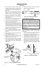
4. Remove 2 connectors from ON/OFF
rocker switch located on wiring harness
(see Figure 17).
5. Insert rocker switch into lower lover panel
with switch lever pointing outward.
6. Reconnect previously removed wire con-
nectors onto switch terminals.
7. Check to make sure power cord is com-
pletely clear of blower and that there are
no foreign objects in blower. Also, double
check all wire leads and make sure wire
routing is not pinched or in a precarious
position. Correct accordingly.
8. Turn on power to duplex outlet if previ-
ously turned off per warning in column 1,
page 14.
9. Plug in blower power cord to duplex outlet
(see Figure 12, page 14).
10. Using ON/OFF rocker switch to turn
blower on and check for operation. Turn
blower off before continuing.
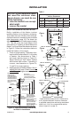
11. Peel off backing paper and stick supplied
wiring diagram decal on rebox bottom
approximately 12" in from of blower (see
Figure 18).
INSTALLATION
Continued
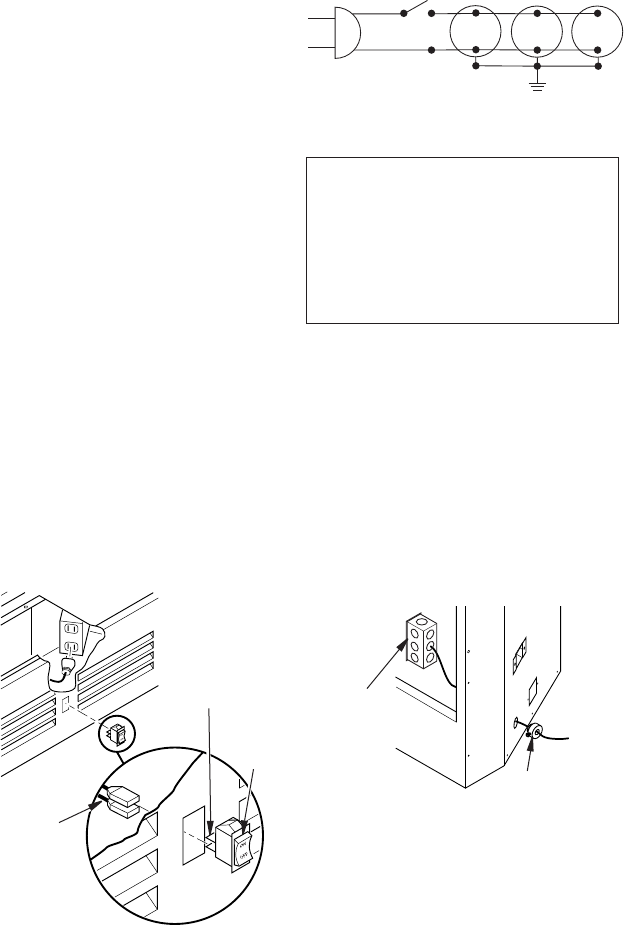
Figure 17 - Connecting Rocker Switch
ON/OFF
Rocker
Switch
Wire Harness
Connectors
Switch
Terminals
Black
110/115
V.A.C.
Blower
Motor
No. 1
Black
Hot
Nuetral
ON/OFF
Panel Switch
Blower
Motor
No. 2
Blower
Motor
No. 3
Figure 18 - BK3 Wiring Diagram
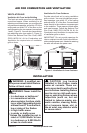
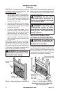
HARD-WIRING FIREBOX
-
The National Electric Code ANSI/
NFPA 70.
The “Handy Box” with duplex outlet is pro-
vided in the rebox located in the lower right
base area.
1. Remove screw holding duplex outlet cover
to handy box. Remove duplex outlet.
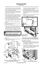
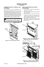
2. Route electrical cable through strain relief
and handy box (see Figure 19).
3. Connect electrical cable to duplex outlet.
Match wire colors to those on duplex out-
let. Be sure to connect the ground wire.
4. Place duplex outlet back into handy box
and secure with screws. Replace outlet
cover.
Strain Relief
Duplex Box/
Handy Box
Figure 19 - Hard-Wiring Firebox
12. Replace all panels and/or brick bottom
panel if previously removed.