


www.fmiproducts.com
108662-01L 11
55
5
/
8
"
39
3
/
8
"
34
1
/
2
"
27
3
/
4
"
0" CLEARANCE
0" CLEARANCE
*10
1
/
2
"
*10
1
/
2
"
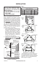
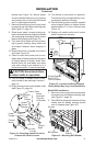
* These dimensions allow for min. Clearances to
a 45° projected side wall. However, clearances
to projected mantel trims and facings are allowed
within a min. Of 16" to a perpenducular wall as
shown in figure 5, on page 10.
*14
1
/
2
"
50
3
/
8
"
71
1
/
4
"
35
5
/
8
"
41
1
/
2
"
0" CLEARANCE
48"
82"
58"
*17"
41"
*17"
FOR 32" MODELS
FOR 36" MODELS
FOR 42" MODELS
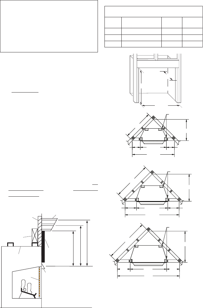
INSTALLATION
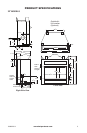
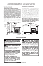
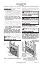
Figure 6 - Minimum Mantel Clearances
for Built-In Installation
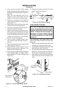
Supplied
Firebox Hood
Must Be Used
at All Times
Wire-mesh
Screen
Firebox
Noncombustible
Material May
Project Off this
Surface above
the Firebox Hood
Mantel Shelf
Note: Any portion of the
mantel shelf must NOT
extend beyond this profile.
12" 16" 20"
1
1
/
2
"
6
3
/
4
"
12"
Note: All vertical
measurements are
from top of fireplace
hood opening to
bottom of mantel shelf.
These minimum
clearances replace any
other recommended
clearances supplied
with your ANSI Z21.11.2
approved gas logs.
Wall board or facing
material (above
firebox) may be of
combustible material,
including decorative
mantel ornaments or
other similar projec-
tions off of the facing
material.
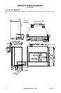
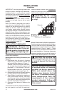
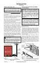
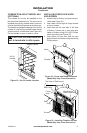
Framing
Material
Built-in Installation
Model
Front Width
(Inside to Inside) Height
Depth
(Min.)
32" 34
7
/
8
" 36
3
/
4
" 16
1
/
4
"
36" 41
1
/
2
" 40
1
/
2
" 20
3
/
4
"
42" 48
5
/
8
" 44
1
/
2
" 22
5
/
8
"
Depth
(Minimum)
Width
(Inside to Inside)
Height
Figure
7a
Figure
7b
Figure
7c
Figure
7d
NOTICE: If your installation does
not meet the minimum clear-
ances shown, you must do one
-
BUILT-IN FIREBOX INSTALLATION
Built-in installation of this rebox involves
installing rebox into a framed-in enclosure.
This makes the front of rebox ush with wall.
Optional brass trim accessories are available
(see Accessories, page 18). The brass trim
will extend past sides of rebox approximately
1/2". This will cover the rough edges of the
wall opening. If installing a mantel above the
rebox, you must follow the clearances shown
in Figure 6. Follow the instructions below to
install the rebox in this manner.
1. Frame in rough opening. The rebox fram-
ing should be constructed of 2 x 4 lumber
or heavier. Use dimensions in Table 1
and rough opening layout in Figure 7a.
Adjust framing so that firebox flushes
with nished wall surface. If installing in
a corner, use dimensions in Figures 7b,
7c and 7d for rough opening.
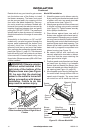
2. Install gas piping to rebox location. See In-
stalling Gas Line, page 12 and Connecting
to Gas Supply in log set owner’s manual.