


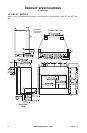
www.fmiproducts.com
108662-01L14
INSTALLATION
Continued
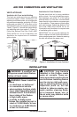
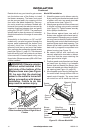
Decide which way you intend to gain access
into the bottom rear of the rebox to install
the blower accessory. The lower front panel
can be removed easily by snapping out the
front with a at blade screwdriver. Use cau-
tion not to scratch any surfaces. Models with
louvered front panels can also be removed by
inserting ngertips between slots and gently
pulling out. DO NOT FORCE. The panels are
actually held in place by means of a retention
dimple embossed on the edge of removable
panels.
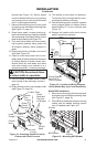
Accessibility to the bottom on 36" and 42"
models only, can also be gained through the
access panel underneath the bottom front
refractory brick liner. Lift the bottom front
refractory brick liner up and out of the rebox
oor, exposing the rectangular shaped access
panel (see Figure 11, page 13). The sides and
back refractory brick liner pieces do not have
to be removed. Lift access panel out by using
nger holes. Blower accessory BK or BK3 can
now be installed.
electrical outlet installed in the
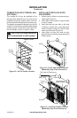
Model BK Installation
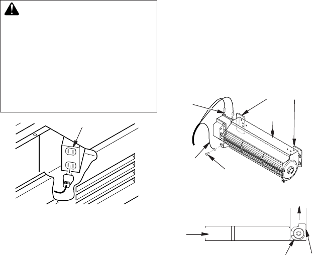
1. Attach the power cord to blower motor by
rmly pushing two female terminals at end
of power cord onto two spade terminals
on blower motor (see Figure 13).
2. Attach green ground wire from power cord
to blower housing using screw provided
(see Figure 13). Tighten screws securely
with a phillips screwdriver.
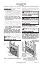
3. Place blower against lower rear wall of
rebox outer wrapper with exhaust port di-
rected upward. Depending on your model,
you may have to carefully route the blower
assembly past controls and brackets and
position blower inside back opening. The
blower will be held in position against the
back wall by magnets incorporated onto
blower housing (see Figure 13).
4. Be certain that all wire terminals are
securely attached to terminals on blower
motor and that the screw retaining the
green ground wire is tight.
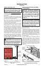
5. Position speed control bracket over ange
on hearth pan by sliding it up between
rebox face and hearth pan ange, then
down until seated onto lower ange of lou-
ver opening (see Figure 14, page 15).
6. Mount speed control box by placing plas-
tic control shaft through bottom hole on
speed control bracket. Top screw head
on control box will t inside top hole on
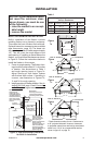
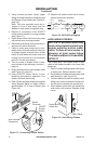
Duplex Electrical Outlet
Figure 12 - Accessing Duplex Electrical
Outlet Installed in Bottom Right Side of
Firebox
Figure 13 - Blower Model BK
Magnetic Strips
Exhaust
Port
Screw
Green
Ground
Wire
Spade
Terminals
Side View
Firebox Bottom
Air Flow
Direction
Blower
Installed
After
Lower
Panel
Removed
Blower
Location
Magnets