


www.fmiproducts.com
108662-01L12
IMPORTANT: If installing blower accessory
(circulating models with louvers only), see
Hard-Wiring Firebox, page 16.
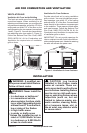
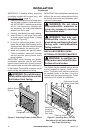
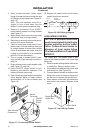
3. Carefully set rebox in front of rough open-
ing with back of rebox inside wall open-
ing. IMPORTANT: If installing a perimeter
trim kit, see instructions included with
trim accessory. You must install shoulder
screws from trim kit now.
4.
Carefully insert rebox into rough opening.
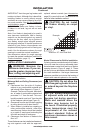
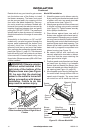
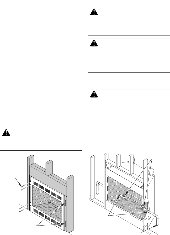
5. Attach rebox to wall studs using nails
or wood screws through holes in nailing
ange (see Figure 8).
6. If using an optional perimeter trim kit,
install the trim after nal nishing and/or
painting of wall. See instructions included
with trim accessory for attaching trim.
7. Install and properly test gas log heater.
Follow installation instructions included
with the vent-free gas log heater that is
being installed.
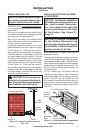
IMPORTANT: When nishing your rebox,
combustible materials such as wall board,
gypsum board, sheet rock, drywall, plywood,
etc. may be butted up next to the sides and top
of the rebox. Combustible materials should
never overlap the rebox front facing.
WARNING: Do not allow any
INSTALLATION
Continued
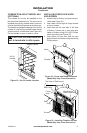
Figure 8 - Attaching Firebox to Wall Studs
Nailing
Flanges
Nails or Wood
Screws
IMPORTANT: Noncombustible materials such
as brick, tile, etc. may overlap the front facing,
but should never cover any necessary open-
ings like louvered slots.
WARNING: Do not allow
WARNING: Use only non-
-
INSTALLING FIREBOX USING
OPTIONAL ACCESSORY MANTELS
-
This rebox may be installed using a cabinet
mantel accessory against a wall in your
home. The rebox and cabinet mantel can
be installed directly on the oor. A trim kit is
included with the mantel accessories. Follow
instructions with mantel for installation.
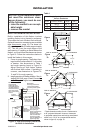
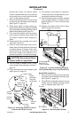
Figure 9 - Installing Gas Line and
Equipment Shutoff Valve (Model May
Vary From Illustration)
Knockout
Locations
(Knock Out
One Hole)
Gas Line Hole
Equipment Shutoff
Valves (Install One)