


cating you are under the limit. (See Figure 2 for cable
connections)
To run the V300 system in 4-20 mA mode, simply turn
the Mode Switch to "4-20 mA" using a screwdriver.
(See Figure 1)
4-20 mA current input specifications:
Isolated input: limited to ± 30 VDC from
earth ground.
Input current range: 0-20 mA
Input voltage at 20 mA: 3.8 V
Max. Rate (100.0%): 20 mA
Min. Rate (5.0%): 4.8 mA
Interface Linearity: 1.5%
Accuracy: 1%
Caution:
If power is applied to the control unit
while in 4-20 mA mode, the motor will start automatical-
ly if the input current is 4.8 mA or above.The "STOP"
and "RUN" buttons will stop and start the pump while in
the 4-20 mA mode however the up down arrows are
not functional in this mode.
3.3 Fluidic Set Up
There are a variety of Pump Head Module(PHM)
configurations available for the V300 system.
Specific instructions are included with each configura-
tion. It is important to follow the instructions included
with the PHM to insure correct operation.
All fluid connections should be completed prior to mov-
ing on to the next steps. In most cases, the pump can-
not be run "dry" for more than a few minutes without
damaging.
FOR ADDITIONAL REFERENCES SEE H431 AND
Q431
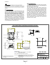
3.4 Connecting the Drive Module
Connect the drive module cable to the control unit's
"PUMP Module" connector. The connector system is a
screw in type that will tighten when turned clockwise.
Tighten the connector hand tight. Do not over tighten,
damage to the control unit and or cable may result,
requiring factory service to repair.
3.5 Connecting to the Main Power (AC Power)
The V300 utilizes a standard "IEC" style power cord.
The unit ships with a North American power cable and
may require a country specific power cable for your
locality. In any case, the V300 must be connected to
an approved grounded outlet of suitable AC voltage
designed for 100 to 240 VAC at 50 or 60 Hz. Your local
distributor can supply you with the proper power cord
for your needs. (See Figure 2 for cable connections)
4.0 Operation
CAUTION CHECK LIST
Make sure the Power Switch is turned off prior to con-
necting the approved power cable to the AC power out-
let.
a) Do not attempt to apply power to the control
unit until all of the above installation and set up
procedures have been completed.
b) Double check reversing and mode switches
prior to turning on the power switch.
c) Since the pump drive module can be a
substantial distance from the control unit, it
is imperative the operator visually verify that
the pump drive module is ready for use and is
not in the midst of some maintenance procedure.
d) If the pump drive cable is disconnected from
the control unit, do not simply re-connect the
cable. Most likely, the pump drive module is
not currently usable due to some maintenance
procedure. The operator must ask the
appropriate personnel to connect the pump
drive module.
4.1 In Manual Mode:
Turn on the AC power switch on the control module.
After a brief initialization period (about 5 sec.) the dis-
play will indicate the current stroke rate setting then
alternate the "OFF" display indicating the control is
waiting for the operator to press "RUN". At this time the
operator may adjust the stroke rate using the up and
down arrows. When the appropriate stroke rate % is
displayed, the operator presses "RUN" to start the
pump. At anytime, the operator may press "STOP" to
shut down the pump. After pressing "STOP" the pump
will remain off until the operator press "RUN". The
stroke rate may be adjusted while the pump is running
in addition to when it is in the off mode. The minimum
stroke rate is 5.0% and the maximum stroke rate is
100.0%. Attempting to exceed these limits will result in
the three dashes being displayed. While in manual
mode, the analog input signal is ignored completely.
4.2 All other Modes:
While the control module is set to one of the three ana-
log interface modes, the control module is controlled by
the reference signal being sent through the BNC cable.
The display will indicate the percent of stroke rate
being requested by the analog interface. For example;
if the interface mode is 0-10 V, and the analog input is
1 V, the display will indicate approximately 10.0%.
These analog input modes are designed to operate
without user intervention however the "STOP" and
"RUN" buttons are active allowing the user to stop the
pump drive and restart the pump after being stopped
by the operator.
!
IN-V300-07
4
!